This manual is the user's manual of the animation software named “Firka”. Only version 26JAN of this software works exactly the same way as described in this manual.
About the version numbering: from the year 2021 onwards, the program version number contains the last two digits of the year, followed by the 3-letter abbreviation of the month (JAN, FEB...). Between 2018 and 2020 years, this latter part was a single letter character and also represented the month of release. Before 2018, the version was a serial number in a “version.subversion” format. The last release used this old version numbering style was 5.0 in 2017.
In the year 2021, this program became free. The free version is mostly similar to the former commercial Professional version. The previously purchased UIC codes are not usable with this free version, since it not requires any identification code to use it. The last commercial version of the program was “21APR”.
Copyright © 2000 - 2026, László Fazekas. All rights reserved.
All rights reserved. Content of this handbook can be freely copied, spread or distribute in printed or in form of electronic information, if its text remains in its full and unchanged form in the result of these operations.
The protected names in this material are trademarks or registered trademarks of their respective holders.
The Firka animation software and the enclosed information material (the Software) is provided on an "as is" basis without warranty of any kind, expressed or implied, including but not limited to the warranties of merchantability, fitness for a particular purpose and nonfringement.
In no event shall the Author be liable for any claim, damages or other liability, whether in an action of contract, tort or otherwise, arising from, out of or in connection with the Software or the use or other dealings in the Software, including but not limited to causing directly or indirectly personal casualty, or for any kind of damages deriving from profit loss.
The contents of this material or the Software itself can be changed by the Author without prior notices.
This handbook or the parts of it and the name of the Author shall not be used in advertising or otherwise to promote the sale, use or other dealing in this Software without prior written authorization from the Author.
The Firka program was originally made for the purpose of supporting pencil test, which is one of the intermediate working phases of the traditional cartoon animation. Computer appears in more and more phases of the animated film creation. This does not mean that the computer take over the creative process itself - there are experiments for it - but this means that in the animation industry, which has always claimed high level of technology background, methods used earlier is replaced with more effective computerized solutions which assure better quality for lower price in the final result.
The rapid growth of computer capability makes it possible that smaller firms or individuals can use a computer of considerable power for a reasonable price. Computerized animation is widely used today in smaller animation companies as well.
In the early 90's Commodore Amiga computers was used for the aim of the line-test, but the capacity of these was too small for a final product of professional quality. Amiga development has stopped in the middle of the 90's, so IBM compatible PC computers have caught up with it, then they rapidly exceeded the graphical capabilities of the Amiga. Meanwhile, the condition of the machine park at the companies has considerably declined.
So it was necessary to develop a modern motion test system, which is suitable for the possibility of today's computers. It had to be able to ease the transition by accepting the data of older pencil test softwares and also be able to cooperate with the fast spreading new painting systems. Additionally, it should be able to expand to a full painting system in the future, taking into consideration the prospective growth of the capacity of the computers.
The Firka software was made for these purposes. Development of the program happened on the basis of the claim of the motion test, the main aim of the author was easy manageability and direct and tangible representation of the motion picture scenes.
With the program, you can create “movies” and scenes within these. One or more exposure sheets (shortly X-sheets, named also as Dope sheets) can belong to the scenes, which are defining the content of each frame of the scene during the playback. The contents can be pictures, sounds, effects or mover paths. The exposure sheet is divided into levels. The order of these levels is important, for example the non-transparent picture content in the upper levels overlap the content of lower levels. There can be virtually unlimited number of X-sheet levels.
The pictures and sounds can be referred only within the scene that contains them. It is possible in the exposure sheet to share level contents between multiple levels, in these cases the changes in one level can appear in the other linked levels as well.
The program stores its scenes in an internal database, but there is a possibility for loading and saving scenes, individual pictures and sound in several different file formats.
The current version of the Firka progam is free of charge, but before the year 2021 it was a paid, commercial software. The former commercial version also had a free mode, which was much more restricted than this new free software. The new version has no paid mode, however you may contact the Author for a customized paid solution, if you need some functionality that is not available in the general version.
To use the previous commercial version, you had to purchase a unique User Identification Code (UIC). For this free version, this is not required anymore. The program do not need any UIC code number to run. The UIC was a code sequence of 3 times 7 characters - letters and numbers.
If you have any questions, please ask the Author of the program:
László Fazekas
Firkafilm Kft. (Ltd.)
6044 Kecskemét, Kikelet u. 39.
HUNGARY
tel.: +36-76+472970
This chapter first describes the required technical equipment, as the computer and its accessories, and then tells about the steps of the installation process, also for computer networks.
The goal of the development for Firka was to make a hardware-independent system. Currently the software is available for PC computers (with MS Windows or Linux) and also for Apple OSX.
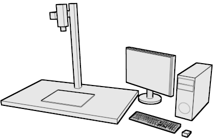
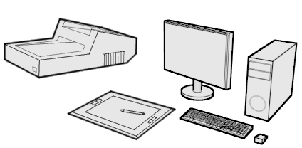
You will need some suitable picture and sound input/output devices to use the program. The picture input is mainly a video camera, or a scanner for painting. The scanner is eventually usable for linetest too, for example to import bigger background sketches.
For linetest, due to its proper speed, video camera capture is recommended. The input device can be some commercial camcorder, industrial or security camera. Place it above a horizontal desk surface, cca. one meter above it. High resolution is important, the camera should have manual zoom, manual focus and aperture. It's also better to adjust white balance manually. Even lighting of the capture surface is also important. The autofocus and auto brightness on the camera can be disturbing, so it's better to switch these off. Also it can be a problem if the camera switches itself off (standby) after a few minutes of inactivity, which usually causes blank picture. Some cameras use this auto off feature only when a cassette is inserted into the camera, or if the camera is working from battery.
Some types of webcameras and photo cameras are also good to use, but usually these provide fewer options to change the parameters. Webcams usually have no zoom.
To convert analogue or digital video signal from the camera into digital data usable by the computer, you will need a video capture device connected to the computer (capture card, frame grabber). Some devices, like webcams, can be connected directly.
It is recommended to put a peg plate on the desk under your camera, where the pegbar is placed on a bigger, movable and usually transparent plate. With manual zoom on the camera the operator can set the field of view, and the field can be positioned by replacing the movable plate under the camera. The bigger plate's weight can avoid an accidental displacement. But if needed, you can seal the pegs position during the capture, for example with adhesive tape.
Sometimes the quality of the movie requires the use of scanned pictures. Specially with camera movements and big backgrounds, when the camera field is too big, the picture from the camera can have poor quality. Even the best cameras have some optical distortions, the edges and corners of the picture can be geometrically distorted, darker, or out of focus. Scanners have no such limitations because of the different working principle. But cameras are used more often because of the faster operation and easy positioning.
When drawings are finished and the linetest approved, it's time to craft the final appearance of the movie. In the traditional animation this means painting the drawings on computer, capturing background paintings, correcting colors, setting the motion paths and field composition, eventually creating effects, and finally rendering the final image sequence, followed by transferring to the final medium (film, video).
Greatly can help this process, if the recorded linetests are reusable during the final compositing. By replacing pictures with better resolution ones and by refining the motion paths, the final material can be finished faster. Reusing the exposure sheet in its unaltered form ensures to preserve every list changes and corrections from the linetests.
The captured materials of the linetest have usually not good enough quality to reuse them in the final material. Lineart drawings must be captured again with a scanner in a resolution matching to the final picture format. A better scanner is fast and can process a sequence of drawings automatically. To process the usual paper sizes of animation, A3 size scanners needed. The Firka program can recognize the position of the drawing by finding the peg holes on the paper. Locking the paper to a position on the scanner during the process is not needed, paper feeders are also usable. Many scanners can use the feeder only with their own software. In this case first record images (as a BMP, JPG etc. sequence) with the scanner's own software, then Firka can process the recorded pictures further.
For recording to the final media, the finished material must be rendered in some standard intermediate format to a data storage, then it can be recorded to the final storage media. This intermediate format can be a special format of AVI for some video recording devices, or usually a sequence of TGA, TIFF or PNG images.
The capacity of today's PC computers are constantly growing. Generally speaking, any kind of new PC computers are suitable to use for both linetest and film making.
The computer preferably must be up-to-date with high capacity. Speed of the microprocessor is usually characterized with the internal clock frequency, which is given in gigahertz units (GHz). Usually the bigger this value is - within one type - the faster the computer will be. Firka can take advantages of multi-core computing too. The size of the inner memory influences also capacity, the more memory your computer has, the more data can be processed with rapid speed.
For camera capture, under Windows you will need a Video for Windows (VfW) compatible capture board or webcam. For Linux, you can use a Video for Linux (V4L/V4L2) or a GPhoto2 compatible hardware. Firka is able to use Firewire camcorders and the Blackmagic Design HD capture cards (DeckLink, Intensity) as well.
For drawing, a pressure sensitive graphic tablet is recommended.
Apple computers are internally similar to PC computers and usually all newer models are suitable to use for both linetest and film making.
Firka can take advantages of multi-core computing too. The size of the inner memory influences also capacity, the more memory your computer has, the more data can be processed with rapid speed.
For camera capture under OSX, Quicktime compatible devices are usable. Firka is able to use the Blackmagic Design HD capture cards (DeckLink, Intensity) as well.
There is also an experimental GPhoto2 support, but not tested yet.
For drawing, a pressure sensitive graphic tablet is recommended.
The program and its related extensions can be downloaded from the
Internet address. On the website you can find an instruction manual for the latest version of the program. If you upgrade your system from the Internet, it is a good idea to download the latest manual also.
First, choose the downloadable packet file for your computer and operating system type. Download it to your computer, and unpack the downloaded file as usually. If you are not familiar with uncompressing, simply send an e-mail to the Author (please notify what is your operating system), and you will get an uncompressed copy by e-mail.
After uncompressing, you get a folder with some files and with an executable program file, named Firka (Firka.exe in Windows environment). You obtain also a text file which introduces your user rights - its name is License. There is also a file that contains the data for installation, themes, language translations etc. Its name is wupdate for Windows, lupdate for Linux and so on. Create a folder (subdirectory) on the drive you want to use for scenes. Copy these files into it. The program will store all its data, including the scenes inside this folder. In this way every data related to Firka can be easily copied, or the program can be finally deleted by deleting that single folder. The program does not modify any of the system settings (registry). The program and the scenes can be carried to any other computer at any time by copying the whole content of the folder. Even if you change the operating system, just you have to overwrite the Firka executable with the suitable version. If you have a dual-boot machine, like Linux and Windows together, you can use the same shared folder for both systems. Just put both executables there.
PREFERABLY DO NOT REINSTALL THE INSTALLED SOFTWARE, OR AT LEAST DO IT BY COPYING THE ENTIRE FOLDER OF THE PROGRAM (THIS INCLUDES COPYING THE SCENES OF THE INTERNAL DATABASE). PREFERABLY DO NOT USE THE OLD COMMERCIAL VERSIONS OF THE PROGRAM IN THE SAME FOLDER TOGETHER WITH THE NEW FREE VERSION. TO UPGRADE THE PROGRAM TO A NEWER VERSION, IT'S ENOUGH TO OVERWRITE THE EXECUTABLE FILE (Firka, Firka.exe). YOU CAN FIND MORE DETAILS IN THIS PART: UPGRADING OF THE SOFTWARE.
Eventually - for example in case of a harddisk fault - you still need to reinstall the software. In this case be very careful to avoid data loss.
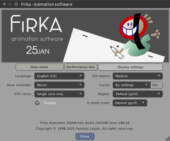
At the first start of the program a warning message appears in a black-and-white window. Click on the Continue button of this window. Then the program starts again, but this time the windows are in their default colors and the program's general settings and information window comes out.
Since the English (US) language version is always at your disposal - it is built into the program code - this handbook refers to the messages and subtitles of the English (US) version.
In this window you can set the language and the user interface theme as well. If your computer has more than one CPU core, you can set the number of cores used by Firka. The program can do some time-consuming operations faster on multiple cores parallely. You can read more about these settings in Chapter 3.3. at the About window.
Close this window by clicking on the Close button.
Capturing pictures
To open the image capture window, click on the Editor button in the main window that appeared at startup, then in the upcoming empty X-sheet window, click on the Record button at the top left corner. Then the capture window will appear.
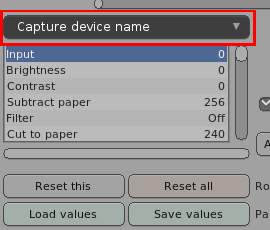
The list with the recognized input devices is located below the image field, at the left side. It looks like a button above the parameters list. Selecting a device here shows its manufacturer's setup window, to select the input channel, the resolution, and the color system - color or black-and-white - for the device. The program will use the picture resolution selected here. The program of the card usually remembers the last settings so it's not required to set again and again.
For most of the Video for Windows (VfW) devices it's not possible to set the maximum resolution this way. To overcome this, use the first element, Input on the parameter list at the left bottom corner. Here you can set the most common HD resolutions.
If an installed picture input device is not on the list, it's likely that the driver software is not properly installed. Check the installed devices in Windows Control Center, to see there is no conflict between devices, and check if all programs were installed from the install disk of the card. Most of the picture input devices are coming with an own digitizer sofware, you can start it also to check the operation of the card.
With the HD capture cards of Blackmagic Design you can connect a high resolution camera to the computer via HDMI or SDI. These are not using the Video for Windows system, but an own driver (it comes with the card and must be installed) and you must set the input format at the Input element of the parameter list at the left bottom corner (the resolution and the frequency, for example, 1080p@24).
With Twain compatible scanners use the Scan in button in the capture window, and keep the captured picture under a name with Capture or Next buttons. Scanners often works well only with their own software, in this case save the scanned pictures into picture files and load these files into Firka.
Capturing pictures
Under Linux the Video for Linux system and its successor, the V4L2 supports various digitizer cards and webcameras.
To open the image capture window, click on the Editor button in the main window that appeared at startup, then in the upcoming empty X-sheet window, click on the Record button at the top left corner. Then the capture window will appear.
In the capture window, below the image field at the left side you can find the list of the recognized devices. It looks like a button above the parameters list. Selecting a device here opens the window of its settings, if there are any. You can keep this window open during the digitizing.
If a digitizer has more than one input, the Video for Linux driver does not select the used video input automatically, you must set it by hand in the capture window, at the first, Input element of the parameters list at the left bottom corner.
You can set the default settings for the Video for Linux devices in the gcnf configuration file.
The program can use GPhoto2 compatible photo cameras but these probably will work only if you first detach the connected camera from the system (using the menu of the appeared device icon on the desktop). With photo cameras use the Scan in button in the capture window to shoot a full resolution picture, which you can save under a name with the Capture or Next buttons. By default the program shows only a low resolution live preview, supposing the photo camera has such a function.
With the HD capture cards of Blackmagic Design you can connect a high resolution camera to the computer via HDMI or SDI. These are using the manufacturer's own driver (it comes with the card and must be installed), and you must set the input format at the Input element of the parameter list at the left bottom corner (the resolution and the frequency, for example, 1080p@24).
Cooperation with the Windows system
If your system is dual bootable to both Windows and Linux, it could be
useful to access the program and its data from both operating systems.
For this, install the program's Windows version into a Windows
storage, and mount this disk under Linux too. Under Linux, make a
folder and copy the Linux version of the program there and start it.
After it created its directory structure, open the “gcnf”
text file from the “var” directory and enter
the following row:
path <The access path of the Windows folder on Linux>
After this the two systems will use the same shared database.
Printing
Under Linux the program prints graphically through the “lpr”
command in Postscript format. If the required programs
(lpd, ghostscript, etc.) are not installed in the system, then the
data types printable as text, like an exposure sheet or a dialog
breaking down, still can be printed by switching off the Postscript
option in the printer window.
When you open the downloaded dmg (Apple Disk Image) file a storage device appears. Opening the contents of this device you can copy the files into the folder you created for the program. There are two separate versions for OSX, a 32-bit and a 64-bit one.
The 32-bit version is a universal binary and it runs on both the newer x86 (Intel) and older PowerPC computers. It is using the Carbon framework. This framework is deprecated and may will not be available in the newer versions of OSX. However, the 32-bit version is still usable under OSX, even on the 64 bit systems, so if you don't need very large scenes (above 4 GB in memory usage), sometimes this version can perform better than the 64-bit version. Also you will need to use it if you want to capture with a Quicktime compatible camera.
The 64-bit version is usable only on x86-64 compatible CPUs. It is using the X11 compatibility of OSX. In older versions of OSX it was built-in, but in newer versions you need to install a package called XQuartz to use it. It is a free, open source software and if it is not installed, the system will very likely offer its installation by itself when you first start Firka. However, newer versions of the operating system (called MacOS instead of OSX) are not doing this, and Firka stops or hangs after started. In this case you need to download the latest version of XQuartz from the Internet and install it manually. It is recommended to enable the “Click through inactive windows” option in the settings of XQuartz, for the usual click-to-focus behaviour of windows.
Capturing pictures
To open the image capture window, click on the Editor button in the main window that appeared at startup, then in the upcoming empty X-sheet window, click on the Record button at the top left corner. Then the capture window will appear.
In the capture window, below the image field at the left side you can find the list of the recognized devices. It looks like a button above the parameters list. Selecting a Quicktime compatible device here opens the window of its settings, where you can select the picture format for your needs.
With the HD capture cards of Blackmagic Design you can connect a high resolution camera to the computer via HDMI or SDI. These are using the manufacturer's own driver (it comes with the card and must be installed), and you must set the input format at the Input element of the parameter list at the left bottom corner (the resolution and the frequency, for example, 1080p@24).
The program probably can use GPhoto2 compatible photo cameras (only the 64 bit version, and it requires libgphoto2 installed) but this function is not tested yet.
The program's user interface consists of the main window which is continuously open while the program is running, and other, temporarily open windows. The close of the main window also exits the program. The appearance of the interface can be changed in the About window by using predefined themes.
The elements of the interface, i.e. scrollbars, lists, buttons, switches etc. are managed uniformly within the program, the keyboard and the mouse can be used in simple general rules.
The operation of the Firka program is based on the usual, mouse-controlled graphical interface of the operating systems. Since the program is a result of a system independent development, its controls are working similarly on any systems. As a result, sometimes the operation of the controls may differ from the usual behaviour of the operating system.
In the program, without the need of completeness, these are the elements of the user interface:
right button menu
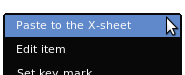
The right mouse button in many cases invokes the menu of the control element, to perform various related operations. You can select from the menu by selecting the menu element and releasing the right button there. You can dismiss the menu by releasing the button outside of it.
scrollbar (slider)
![]()
Scrollbars can be used to scroll through list fields or to set various quantities. You can move the position smoothly with the arrows at the ends of the scrollbar. Sometimes there are small rectangles at the ends of the scrollbars, you can select predefined values with these buttons (for example, standard values). The position can be dragged with the left button of the mouse. Clicking before or after the position results in one unit scrolling (e.g. one screen). You can use the mouse wheel on the scrollbar too. When you press the arrow buttons permanently, it results repeated steps, and this works the same for the regions before and after the current position.
list
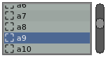
Lists show data sequences. When you click on a list, it becomes active, its border changes. Then you can also use the cursor keys on the keyboard to control it. In this case the Space key substitutes a clicking on an element. For double clicking, use the Return/Enter key. You can scroll the list by dragging it with the middle button of the mouse. Also, you can use the the mouse weel for scrolling.
button
You can activate various commands with buttons. The button can be activated by press or by release and it may contain a menu. Clicking on a release activated button is valid only if the mouse pointer is still on the button when the mouse button is released. So you can abort a mistaken button click. The button types:
normal button
![]()
- you can activate a command by clicking on it,
menu button
![]()
- when you click on it, a menu appears. You can select a menu element by releasing the mouse button on it. Menu buttons can be used to select the parameter value from multiple choices. The name of the selected menu element will be displayed on the button.
normal button with menu
![]()
- its menu will only appear when you drag the mouse pointer outside the button while holding down the mouse button. Otherwise the button behaves like a normal clickable button. Clicking with the left mouse button usually results the same as the first item of its menu, while Ctrl+Left mouse button, Middle mouse button activates the second menu item.
toggle switch button
![]()
- its state (pressed or released) changes when clicked. In some cases the pressed state of the button indicates that the function, which can be enabled in the window that the button can open, is active.
switch (checkbox)
![]()
A dual state element that lets you turn an option on or off. Only the switch part is active, clicking on the text label does nothing.
three-state checkbox
![]()
- some checkboxes also can be set to a third state with the Right mouse button, Middle mouse button. This activates an optional, different variation of the switched-on state. These checkboxes sometimes have a right-button menu, to choose from the available options.
text field
![]()
Usable to enter single-line text and numeric data. You can activate it by clicking on it, this condition is indicated by its frame and the visible cursor. Use the keyboard to enter into the active text field. The horizontal cursor moving keys are usable to move the cursor in the text. The effect of the vertical cursor buttons is function-dependent, it can often be used to increase or decrease the number before the cursor in the entered text. The numeric value in the text can also be increased or decreased by clicking the small arrows on the right side of the text box. The mouse wheel also can do this.
tooltips (bubble help)
![]()
If the language translation contains the help
file, when leaving the mouse above the control element,
approximately after a second the program displays a short desctiption
about the control element in a small frame beside the mouse pointer.
This disappears when you move the mouse. Displaying of tooltips can be
disabled in the About window.
The keyboard is always in connection with the active window. The frame of the active window usually differ from the other windows. Some control elements can have direct keyboard control, in these cases the control element also must be activated within the window. Generally, if the active control element can handle the key pressed, then the key will be processed by control, otherwise it will affect the window.
For example, if pressing the letter “A” activates a function in the window, this function will be unreachable if there is an active text input field, because it will insert a letter “A” into the text instead. In this case click on any empty part on the window to deactivate the input field, then the original function of key “A” is restored.
The Firka program assumes the use of a three-button mouse, equipped with a mouse wheel. The left button of the mouse must exist, the other buttons can be substituted by using the left button and modifier keys on the keyboard.
Left button
- Command button, to activate or drag the control elements of the user interface. It activates the clicked element, another interface element cannot become active while it is pressed. For some control elements, the clicked control can be dragged while pressing this button. Together with the keyboard it can substitute the right and middle mouse buttons.
Right button
- Menu invoking button, sometimes command button, on displays dragging with this button zooms the view. It can be substituted with the Control + left mouse button combination. It activates the clicked control element.
Middle button
- Command button, dragging with this button scrolls the lists and the display surfaces. It can be substituted with the Shift + left mouse button combination. It activates the clicked control element.
Mouse wheel
- It is usable to zoom and scroll views, and to increment or decrement numeric parameters. It does not activate the control element, and it has effect on inactive windows and inactive control elements too.
The general elements of the user interface include the windows to load and save external files. There are load and save buttons everywhere in the program. With these you can use various file formats to export or import scenes, pictures, sounds, settings, pegs positions etc. The file load and save windows are generally the same in these operations.
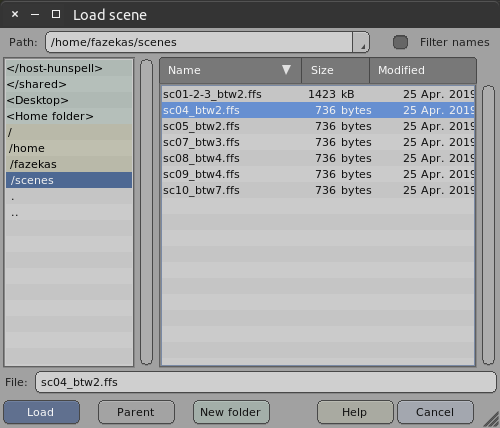
The list on the left side in the window contains the subdirectories in the displayed folder. At the beginning of this list, the program collects some shortcuts for you (connected devices, home folder, desktop). To the right of this, you can see the list of the files. There is a sizer bar between these two lists to resize them inside the window.
The list on the right side has a headline. The fields here are named Name, Size, and Modified. These correspond to each column of the list. You can resize these fields by replacing the separator lines between them. Clicking on a field selects its column for the sorting of the list. A triangle mark shows the selected field at its right side. Repeated clicking on a field reverses the sorting direction.
If the Filter names option is enabled, you can see only the
loadable files (filtered by their name extension, like: .jpg
, .wav , etc.). The .ffs is the
extension for Firka's own scene format, and the .ffd is
the own format for individual items (pictures, sounds, etc.). These
two formats are able to carry all information from these data
elements, while others are portable, but may lose some information.
At the top of the window the Path: input field contains the filesystem path to the current folder. At the right hand side of the this field you can find a menu button with the last used directory paths.
You can enter the filename into the File: input field, or you can click on the files in the list. For scenes and item data, you can select multiple files by clicking and dragging the mouse on the list. You can also select and deselect individual entries with the Ctrl + left button of the mouse. To select the names between the cursor and the clicked scene, use the Shift + left mouse button combination. If you selected the file to load, click on the Load button, or press Enter on the keyboard.
Also you can use the drag and drop functions of your desktop to load files. Drop scene files onto the Scenes... window and it will load them the same way as you do with the Load file button. Similarly, you can import items (pictures, sounds etc.) by dropping the files onto the Exposure sheet window or onto the Record window.
The general elements of the user interface include the windows to load and save external files. Handling these windows is the same, apart from the parameters depending on the file type.
For saving, the requester window usually have some additional controls. When saving scenes, you can see a lot of buttons and checkboxes. You can open this window from the Scenes... window with the Save to file button, or from the exposure sheet window, if you click first on the Save as button, then click on the To file button in the new window.
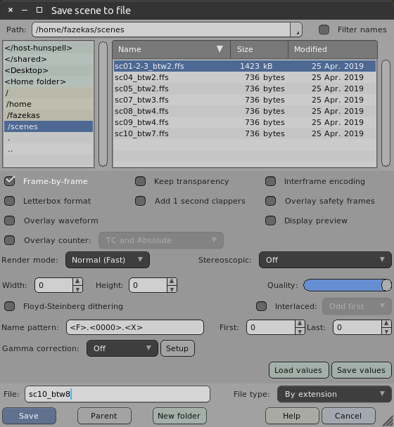
With the File type: menu you can select the file type from the list of the available formats. If By extension mode selected, you can determine the file type with the extension in the filename - for example, .bmp for BMP type files. Otherwise, you can specify the file format directly from the menu.
For pictures, you can set any pixel resolution you want. If both Width: and Height: are zero, the resolution will be calculated from the original resolution of the picture. Otherwise, the resolution will be exactly what you set. If you set only one of width or height, the other dimension will automatically be calculated, based on square pixels.
With the Floyd-Steinberg dithering option you can add a noise-like pattern to get better matching colors. This can be used when the palettes in the chosen format have no more than 256 colors (for example GIF or AVI).
You can use the Interlaced: switch to render in interlaced mode. This mode calculates a motion path separately for the two interlace fields if the Interlaced motion mode was enabled for the path. You can describe which field comes first in time - Odd first, Even first, this must match the specifications of the used video standard. For a better control over interlacing, create and render the scenes with double frame rate instead, and mix the rendered fields in a video editor afterwards.
With the Quality: slider, you can specify a quality value for the encoding. Less quality results lower file size. For some file formats you get an option menu or a checkbox instead of this slider.
For sounds, you can also set the sampling frequency here.
The Frame-by-frame switch is enabled by default and usable if you want to create a file for every frames. Otherwise, the software creates only the frames where the animation changes.
The Keep transparency switch disables the monochrome drop background (the white paper) and keeps the transparency of the transparent pixels.
Enable the Interframe encoding switch to use the equivalences between frames in the encoding, if the file format supports it (GIF, AVI). It could decrease the size of the result file, but sometimes it may not useful if you want to utilize the result frame-by-frame, or with forwards and backwards playback.
The Letterbox format switch is usable together with the Width: and Height: settings. If you specify a width and height, the program normally scales the picture to fill the entire field (occasionally you may need non-square pixels). If the switch is on, the program works with square-shape pixels and uses the width and height values as a frame aspect ratio also. If the shape is not the same as for the scene, the program places black bars onto the edges of the picture, just like when you see a widescreen movie on television.
The Add 1 second clappers or Add 1 frame clappers generates a clappers image before the animation, similar to the clappers on the player window, with color bars, name and length of the scene.
Use the Clappers only switch (this option only appears when the selected file format supports it) to generate only clappers, without rendering any other scene frames. Use this to create, for example placeholder pictures for video editing.
The Overlay safety frames, Overlay waveform and Overlay counter: options are similar to the same functions of the player window, as you can read in Chapter 8.1.
With the Render mode: menu you can select the three draft rendering modes, known from the player window (Normal (Fast), Better, Best (Slower)), and even the high quality mode (Final).
Use the options of the Stereoscopic: menu to render stereoscopic scenes into different stereo formats.
By enabling the Display preview switch, the rendered image will be displayed in a small window during rendering if the file format supports this option.
With the Setup settings you can add color correction to the rendered picture, if needed.
In the Name pattern: field you can enter a naming scheme for the numbered sequence of images. Combine these keywords, perhaps with inserted additional characters:
<F> - scene number from the name of the scene,
<N> - scene name (or the name of the exposure sheet
if not saved yet),
<D> - logfile/folder name (without extension),
<Gname> - with //file , the level
group, otherwise the letters after G ,
<number> - numeric format for serial numbering,
<X> - name extension of the file type.
In the numeric format you can control the number of written digits with the number of placeholder zero digits in the pattern. However, if the given serial number has more digits than the number of placeholder zeroes, it will be as long as it's needed. If the value of the numeric format is not zero, it will be added to the serial number of the frame. The numbering of frames starts from 1 and increases one by one.
If there is a % (percent) character at the end of the
numeric format (for example “0000%” ) then after
adding the value to the frame number, a timecode is inserted
to the name, in a “hours.minutes.seconds.frames” format.
It's calculated based on the play speed. The numeric fields are two
characters long, any given placeholder zeroes are ignored. The
timecode starts from 00.00.00.00 and increases one by
one.
An example:
<D>_<0000>.<X>
In this case, if you save a JPEG sequence and you enter “SC1”
for the filename, this will create a folder with “SC1”
name, a log file “SC1.jtx” in it, together
with an image sequence: “SC1_0001.jpg” , “SC1_0002.jpg”
...
Another example:
<Ga>_<0000>.<X>
In this case, when saving a JPEG sequence and for example, there are
two //file effects on a particular frame of the exposure
sheet, which are saving the levels of the “M” and
“N” level groups into separated folders “M”
and “N” , then there will be “M_0001.jpg”...
style filenames in the “M” folder and “N_0001.jpg”...
style filenames in the “N” folder.
Otherwise, if there is no //file effect on the frame,
the format will be “a_0001.jpg”... .
If you don't want to create an additional folder for this sequence, use
“SC1.jtx” for the filename. The “.jtx”
part is the extension of a JPEG sequence logfile in the
program. Based on this, the program can recognize that you entered a
logfile name directly and also that you want to save JPEG files.
You can use the Load values and Save values buttons to store and restore the combination of settings.
This window is generally the same as the file load window, only it is usable to select a folder (subdirectory) instead of files.
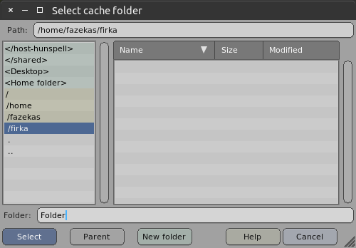
To select an existing folder, click on its name in the left side list. The selected name will appear in the Folder: input field. By double clicking, you can step into the folder, in this case the Folder: field becomes empty.
The selected folder will be the combination of the Path: (parent folder) and the Folder: fields. If the Folder: field is empty, the content of Path:, e.g. the currently viewed folder will be the result. If you want to enter a new folder name that is not exists yet, step into the parent folder and enter the name into the Folder: field.
After you finished the selection, click on the Select button to close the window.
The Firka program has a window, let's call it main window, which always opens at the start of the program and it remains open all along. Exiting this window finishes the running of the program.
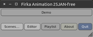
These are the buttons of the main window:
First button
it shows the name of the currently selected movie and opens the movie selection window.
Scenes...
opens the scenes window of the movie.
Editor
opens an empty, unsaved exposure sheet window.
Playlist
opens a window to manage concatenated scenes.
About
opens the program information window. You can change some basic settigs, like the language and style of the user interface.
Quit
and you can quit the Firka program with this button.
On the main window the About button opens this window, and it is similar to the window opened after the installation, when the program started the first time.
The upper part of the window contains a welcome picture. This picture is always displayed acoording to the seteoscopic 3D display settings of the settings in the Play window. If you set a stereoscopic display mode for the player window, this picture also will be displayed with the same mode.
With the Data sheet button you can check the configuration of the program.
There is a Performance test button to check the play speed capabilities of your hardware.
With the Display settings button you can adjust the color correction for displaying.
With the Language: menu button you can select the used language. Changing the language means that the texts change into the translated one, but the place and function of the interface elements remains the same.
In the GUI theme: menu you can select from the installed user interface themes. The selected theme defines the color and look of the control elements and also the styles of text fonts.
By setting the Save reminder:, the program will give you a warning message if modifications to a scene have not been saved until the end of the specified time period. Then you can choose to save it over the original file, or as a new version, or as a temporary save, just for the case the program crashes. The temporary save will be deleted after the next real save.
With Cache: you can define a background storage area, which relives the program and the memory when handling large pictures. You can read more about its configuration in the next chapter.
The CPU cores: defines how many processor cores can be used simultaneously from the multiple cores. More than one processor core can speed up operations, especially the rendering. The memory bandwidth is often a bottleneck for this kind of acceleration, in this case the use of all cores may not be the optimal solution. If you encounter any instability in the working of your computer, you can try to use the Single core only setting as well.
The Pegbar: setting defines the behaviour when creating pegbar positions and new picture items:
Nothing / bottom - the default pegbar position is below the image field. When you create or load a new picture item which has no pegbar position by itself (for example when you load a simple picture format, like JPG or BMP), there will be no pegbar information attached to the picture item,
Bottom pegbar - the default pegbar position is below the image field, and all new picture items will get a defined pegs position.
Top pegbar - the default pegbar position is above the image field, and all new picture items will get a defined pegs position.
If you have a picture without pegbar information, and you place it on a pegbar, its position by historical reasons will match to the bottom pegbar. So to use a top pegbar correctly, the picture item should have its own and corresponding pegbar position, otherwise it will appear upside down.
The X-sheet order: defines the order of levels in the exposure sheet views. By default it is from left to right, which means the bottom level is the leftmost column of the exposure sheet.
With the Tooltips switch you can switch on and off the displaying of tooltips. The tooltip or bubble help appears when the mouse pointer remains over a control element on the user interface, and shows a short description for the element.
Although today's computers can process huge amounts of data, managing a high resolution color movie is still a challenge. When the external cache is enabled and you load a scene for editing, the program selects all pictures larger than a threshold, and temporarily puts them into files on the harddisk. Only reduced resolution copies remain in the computer's internal memory. During playback, there is an option to use the original or the reduced pictures for rendering. Using the reduced pictures can radically speed up the program when editing complex scenes. Also because it uses less memory, larger scenes and higher resolution images can be manageable.
But a disadvantage is, that the processing of the original resolution pictures becomes slower because the program keeps these on the storage device. The loading and saving of scenes also becomes slower.
By default, this feature is inactive. To use it, make an empty folder on a rapidly readable-writable partition (preferably on a fast local drive) where there is enough space for the temporary files. On a network it is practical to make separate cache folders locally on each computers.
In the About window, use the menu of Cache: to switch on and off the cache function:
Default (gcnf) - default settings by the “gcnf”
configuration file,
Cache off - disabled cache,
By settings - enabled cache.
In Default (gcnf) mode, the contents of the “gcnf”
configuration file will be used. If no cache defined there,
then the cache will be switched off. You can read how to configure the
cache in “gcnf” in Chapter 10.2.
If the By settings is active, the parameter window can be opened with the Set... button, next to the menu button:
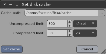
In the input field next to the Cache path: label you can specify the folder for the temporary files of the cache. These files are there only while the program is running, the program deletes them when quit. Click on the small button at the right edge of the input field to open a folder selection window, where you can select the required folder.
With Uncompressed limit: input field you can set a limit value, which can not be exceeded by the number of pixels in an image. If a picture in the memory is larger than this, the program will put it in the cache and will keep a reduced resolution picture in the memory, which is not larger than the limit. For example, the size of a full-HD image (1920x1080) is cca. two megapixels.
The Compressed limit: defines a memory size, which can not be exceeded by the compressed size of the picture. The program uses lossless comresion on the images, the more complex the content of a picture is, the more space it occupies and the more time it takes to work with. This limit value can restrict the detailed and complex pictures that slow down playing. The program achieves this with a further reduction in the resolution.
Next to both fields, the scale of the given value (kilo, mega) can be set.
The Set cache button closes the window and applies the settings. If the specified folder does not exists yet, it will attempt to create. It is important, that the folder does not begin to work immediately, only after restarting the program. But the program uses the limit values immediately for the new loaded and modified pictures.
When closing the About window, the program will warn you if you need to restart it because of the folder path change.
The usable maximum playback speed depends on the graphic mode and the picture resolution. Measuring the play speed is important to correctly set up the program, to compare the capacity of the possible graphics modes. It's not worthy to choose a resolution or color depth if it overloads the computer and obstructs the precise playback of scenes.
In the About window the Performance test button starts the speed measuring test. The picture field of the window is flashing for a while, then you get a message with the result. The program measures two parameters: the first one is the common performance of the CPU and the videocard for real-time playing with uncompression. This is the more important parameter and usually it must be at least 35 frames/second. The second data shows the highest possible frame rate.
Because the color settings are different on display devices, sometimes there is a need to calibrate and correct the displayed colors. To support this, in the About window, there is a window you can open by Display settings button. Here you can set separate color corrections for the playing on windows - Window, for fullscreen playing on external device - Fullscreen, and there are two settings for saving to file - Video and Film.
An external display device can be a special hardware display, another monitor, video recorder etc., it depends on the operating system and the settings of the Firka program. In this window you can enable or disable the fullscreen playing on the configured external device, with the Fullscreen on external device option. If it is disabled, the fullscreen playing uses the settings of the working screen windows, i.e. the Window settings, and the fullscreen picture will cover the windows on your screen.
The display devices are usually working in sRGB color space and Firka is using this too. There are two main distortions you can correct: the gamma and the transient (high frequency) distortion. The gamma is the nonlinearity of the brightness of the monitor pixels, and the transient distortion is visible where the picture contains high frequency components in the horizontal scanlines (like a thin vertical line).
You can enable the color correction with the Color correction enabled switch. If it is on, you can modify the minimum, middle and maximum levels of the color components, and the transient equalization. Usually it is enough to set the middle value according to the required gamma correction, and if the white balance is correct you can set all three color components to the same.
An additional possibility to use the Transient: slider, with this you can enhance the high frequency components, if the display device suppresses them. With good quality monitors it's unnecessary to use other than zero for this value.
You can check the settings with the color bars, it is correct if all the fields seems equal for each color components.
With Load values and Save values buttons you can load the entire settings from an external file, or you can save it there.
In the program, the scenes are arranged into folders, called movies. A movie has some common settings for all of its scenes. These are immutable by individual scenes, but global for the entire movie. Parameters like the field shape, the default screen resolution and the frame rate of playing. It is also possible to manage the access of the users to the movies.
The first button on the main window opens the window of the movies. The label of this button is always the name of the selected movie. The window which can be opened by the Scenes... button shows the scenes of the selected movie. If you select a different movie in the movies window, the window of scenes also swaps to the contents of the selected movie. If you double click on the movie, it opens the Scenes... window too.
To create a new movie, in the Movies window first open the hidden controls by clicking on the More control button. Then enter the name of the movie into the Name: field and after that click on the New button. This button also has a menu to select from some standard movie formats. By default the new movie copies the settings of the currently selected movie. If you enter a password into the Password: field before creating the movie, the user will have to enter this same password into this same Password: field to get access to the settings and to the scenes of the movie.
If you want to use an already existing name, the program gives you an error message.
In the Movies window there is a More control button below the list of the movies. By clicking on this button you can view the settings of the selected movie.
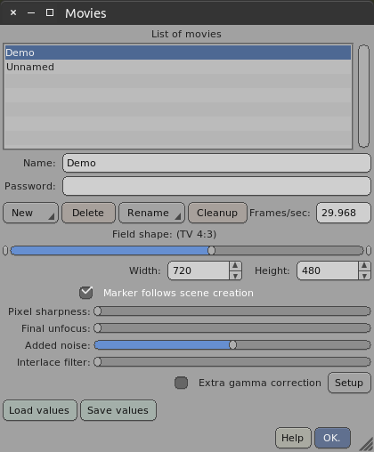
The Delete button deletes the selected movie. This is a very dangerous operation because it also permanently deletes all scenes of the movie.
With the Rename button you can change the name of the movie and by using its menu, the format settings too. With the renaming you can also give a password to a previously unprotected movie. The menu of the button contains a Clear password option if you want to remove the password protection from a movie.
The Cleanup button removes all safety copies of the scenes from the movie. These are the penultimate versions of the scenes. This command frees up approximately the half of the allocated disk space so you can use this when your harddisk is full and you need some extra disk space.
You can enter the frame rate of the movie into the Frames/sec: field. Decimal fractions are accepted. Under this the Field shape: slider and the Width: and Height: fields are defining the shape and default pixel resolution of the movie format. These settings and the others below are changed instantly, no need to use the rename function to validate the changed values.
If the Marker follows scene creation enabled and you save an existing scene under a new name, it clears the little dot mark of the old version and marks the new saved scene. The new scene also gets the old scene status marking (LAYOUT etc.).
The next sliders: Pixel sharpness:, Final unfocus:, Added noise:, Interlace filter: are parameters for the final quality rendering and usually there is no need to change them.
By setting the Extra gamma correction parameter you can add a color correction to the rendered frames of the movie. These settings are similar to the color correction settings on the About window.
With the Load values and Save values buttons you can load the movie settings from a file or you can save them to file. The saved file contains the color palettes of the movie as well.
In the animation making multiple users should have access to the database of scenes. The linetest operator, the director, the animators and inbetweeners all need some freedom to handle the scenes.
Of course this is a hazard as well. The Firka program has built-in functions to manage the scenes database, including to delete and overwrite scenes. If anybody can use these tools, accidentally or willfully can cause serious damages. Because of this, in the Firka program there are multiple levels of protection for the individual movies.
A user logs in to the operating system with a username and perhaps with a password too. The username based protection is based upon this login name, so the users should use individual names to log in to their computers, at least for each access right categories.
If the “var/tilt” file is
containing the owner keyword then the access rights are
managed by the user names. The security will be complete only when the
“var/tilt” file is only readable for the average
user. User names given after the owner keyword are the
keepers of the database and they can freely edit the contents
of any movies.
If the user not belongs to the keepers, one of these groups can be applicable on the user for a movie:
owner
by default the owner is the user who created the movie. The keeper users are able to change the name of the owner, and also they can add more owners. The owner cannot do this. But the owner has rights to change the properties of the movie and to delete the movie. If a movie has no owner defined, it means there are no such users and only the keepers can modify the movie.
read-write
by default all users who are not a keeper and not an owner, belongs to this group. These users have the rights to delete, rename, overwrite and create scenes, but the movie parameters (frame rate, resolution...) are prohibited for them and they cannot delete the movie itself.
read-only
these users can load the scenes of the movie but they have no rights to
overwrite or create scenes, and obviously they cannot modify the
movie. But they have rights to save the scenes into external files, so
the total write protection against them is only possible with a
combination of this and other functions of the
“tilt” file. After all, there is an option also
for the Read-only users to save the modified scenes in the movie with
a new name.
disabled
these users have no rights to access the movie at all. They can see the movie on the list but they cannot activate it, so they cannot access its contents.
You can reach the controls to change these user groups after you clicked on the More control button, but only if the username protection mode is active.
In the user groups, just like in the “tilt”
file, you can use a space character as a separator between
the names. You can use special wildcards :
*
the asterisk means all users, the characters after the asterisk will be
disregarded. For example, A* means all of the users
whose names beginning with the “A” letter.
? or !
nobody belongs to this group. There is no reason to use it alone, only
after some characters. For example A? * means everybody,
except the names beginning with the “A” letter.
|
similar to the space character. If you use this separator between name, the program will group the names together, it has a meaning of the special variety of the read-only access, see it below. Do not put space between this character and the separated names.
If a keeper is running the program, the Owner: field is containing the name of the owner(s). For the other users this field is not visible.
You can enter read-only users into the Read-only for: field. For these users there is a special access mode which can be activated with the “Read-only” can save new scenes option. It permits to save the modified scenes under a new name in the protected movie. For this, the program remembers the last saver read-only user. If the same user editing the same scene later, the program allows to overwrite the scene (but not to delete!), otherwise the user can save only when creating a new scene. Then the user, as the creator of this new scene, will be able to modify the scene afterwards.
The | character between the usernames, or the
* character puts the selected users into the same
group. Users in the same group have the right to overwrite scenes of
their fellow members of the group.
The usernames in the Disabled for: field have no rights to access the movie.
The movie has another protection level beside the username based protection. This requires a password, so it can restrict the access of the keepers too.
When creating or renaming a movie, and you enter a password into the Password: field, afterwards you will have to enter the same password to be able to modify the movie or its scenes.
With this solution you cannot change the password. If you want to delete the password (afterwards you can add a new password with a rename), first enter the old password and click on the Rename button with the Ctrl+Left mouse button, Middle mouse button, or select the Clear password option from the button's menu. This clears the password.
Forgetting the password could make impossible to edit the movie in
Firka, so there is a detour: in the “var/admin/dfmv”
file, after the name of the movie in the row beginning with P:
you can see the password as an open text. Anyway, it is
already recommended to protect these files against the direct access
from the filesystem.
The scenes of a movie usually share a common play format, which is the same for the entire movie. That's why these settings belong to the movie and not to the individual scenes.
The movie format is determined by these parameters:
- playback speed, in frames/second,
- field aspect ratio,
- horizontal and vertical pixel resolution of the picture field.
There can be cases when a scene must have its own format, different from the common format of the movie. For these situations, you can use the format override settings.
Sometimes you need some extra frames at the beginning or end of the played time interval on the exposure sheet. For example, when the last cycle of a repeated mover path ends after the last frame of the scene, or the motion starts from an internal frame of the cycle at the beginning of the scene. In this case it is useful if you can add frames that are not part of the played interval, to the beginning or end of the scene.
By default, the playback starts at the first frame of the exposure sheet, and ends on the last frame of the longest level. But you can override this as well:
- by specifying the first and last frames of the playback interval.
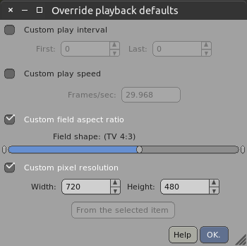
In the exposure sheet window, the menu of the Play button contains the Override playback format item to open the window and override the playback defaults.
The override belongs to the current exposure sheet and will be saved together with the scene. If a scene contains more than one exposure sheet, each of them can have separate override settings.
It is important to know that if you play or render a scene in the Playlist window, the program ignores the speed and field overrides there, and always uses the format from the movie only. This is so to ensure the compatible format of the concatenated scenes.
To override a parameter, first enable the customization on it, then you can modify the value of the parameter.
The Custom play interval switch enables overriding the first and last frame of the playback with the First: and Last: input fields. If you want to keep the default end of the scene, set the value of the Last: field to 0. The given interval will be applied when exporting the scene and in the Playlist window as well. In the X-sheet, the part outside of the playback range is indicated by lighter, inactive colors of the side numbering columns.
With the Custom play speed switch you can override the play speed. Just like for the movie settings, enter a frames/second value. You can also use decimal fractions.
Switching Custom field aspect ratio on overrides the aspect ratio of the image field. Similar to the movie settings, you can use a slider to set the field shape. With the two small buttons at the ends of the slider and with its right mouse button menu, you can select from various standard formats.
Use the Custom pixel resolution switch to override default pixel resolution of the image field. By clicking with the right mouse button on Width: or Height: input fields, you can select some standard resolutions from the menu.
By saving the scene, these settings will be saved into the scene and remain in effect afterwards.
With the From the selected item button you can copy the aspect ratio and the resolution from a picture or morph type item into the override parameters. To use this feature, first select a picture or morph item on the right side list in the exposure sheet window.
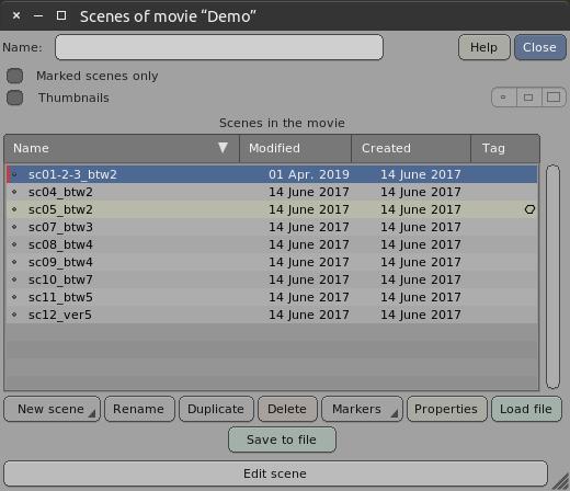
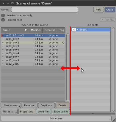
You can open the window of scenes in the main window by clicking on the Scenes... button. Then a window appears, with the list of scenes from the currently selected movie below the Scenes in the movie label. After the first starting this list is empty.
On the right side of the window there is a hidden list with X-sheets label, for the the exposure sheets of the selected scene. It is hidden because normally not used at all, but you can show it if you drag the sizing bar to the left from the right side edge of the window. Below these lists, you can see buttons also. These buttons are operating on scenes.
The list of scenes has a headline with Name, Modified, Created and Tag fields. These are the columns of the list. The width of these fields can be changed by dragging the separator edges of the fields. Clicking on a field selects it as the aspect of list sorting. A small triangle at the right hand side of the field shows this selection. Repeated clicking on a field reverses the sorting order, and the triangle is also turning over. If the Name column selected, the list will be sorted alphabetically, or it will be sorted by the modification dates with the Modified, and so on.
At the bottom of the scenes window, you can see the control buttons belonging to the scene. With the New scene button you can make a new scene. First enter a name into the Name: field. Use the Rename button to change the name of the selected scene, Duplicate makes a copy of the scene, and Delete deletes the scene. Use the Properties button to query the parameters of the selected scene.
The scenes can be marked with small squares in front of their names on the list. By using the Markers button, or by clicking the left mouse button on the place of these marks on the list you can switch on and off these small marker squares for the scenes. If you use these to mark only the latest versions of the scenes, you can hide the previous versions of the scenes on the list, by using the Marked scenes only option.
Some buttons have an optional menu in the program. The button works as a normal button if you click on it. The menu appears only if you keep the mouse button pressed and move the mouse away from the button. These menu buttons have a small triangle at the right bottom corner.
In this window the New scene and Markers buttons have optional menus.
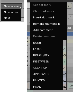
In the New scene button menu, the Next command (you can reach this same function without the menu by using Ctrl+Left mouse button, Middle mouse button to click on the button) first adds one to the numeric part of the content in the Name: field, then creates a new scene with the modified name. It can be useful if you need to create multiple scenes at once.
In the Markers button's menu, the Set dot mark, Clear dot mark, and Invert dot mark elements are manipulating the small marker in front of the scene name.
The Remake thumbnails command recalculates the miniature pictures for the selected scenes. For example you may need this after you changed the field aspect ratio of the movie.
You can find the Thumbnails switch at the top part of the window. Here you can enable or disable displaying of the miniature thumbnail pictures in the scenes list, and also in the X-sheets list. The program makes a thumbnail picture from the middle frame of the X-sheet when the scene saved.
The Add comment menu element attaches the text in the Name: field to the selected scene as a comment text. On the list, a little marker at the left side of the scene name indicates if there is a comment. You can read this comment in a bubble if you place the mouse above this marker on the list. You can delete the comment with the Delete comment menu item or with the Add comment item together with an empty text. Both menu items are applicable to multiple selected scenes. You can copy the comment text of the actual scene into the Name: field by clicking on the Markers button with Ctrl+Left mouse button, Middle mouse button.
The other elements (NONE, LAYOUT etc.) can be markers for the scenes to show their actual state, and the program shows these on the list with small symbols and colors.
Use the Load file and Save to file buttons to load or save external scene files in various formats. Also you can load these files by using the drag and drop functions of your desktop: drop the icons of the files onto the Scenes... window.
You can select more than one scene for an operation at the same time, just click on the first scene and move the mouse with pressed button across the scenes. Also you can select them one by one with the Ctrl+Left mouse button, or you can use the Shift+Left mouse button to select every scenes between the cursor and the clicked scene. Serial numbers become visible for the selected scenes, to be easier to count them.
To open the exposure sheet window for a scene, click Edit scene button.
When creating a new scene, it will be placed in the active movie, so check the label of the first button on the main window, to ensure which movie is selected. If you want to switch to another movie, click on this first button of the main window and select (or create) the required movie in the window of movies.
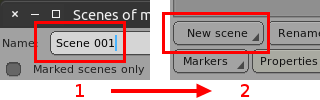
After this, in the Scenes... window, first enter a name for it
to the Name: input field. First click on it, then type in, for
example: First scene . By clicking the New scene
button under the Scenes in the movie list, you created a new
scene and it appears on the list. An empty exposure sheet is also
created for the scene, which appears on the right side list, in case
if it's visible.
By clicking twice on a scene you can open it for editing. The Edit scene button below is also usable for this.
The exposure sheet is a table that describes what to do on the frames of the scene during the playback. A scene usually has one X-sheet, but there can be more. These can be, for example different versions of the scene when it has not yet been decided which will be the final version. But this can be useful when multiple scenes use the same pictures, pegbars, movers, and these scenes can be created as different X-sheets of the same scene.
When a new scene created, an exposure sheet is also made for it. To add another ones, use the buttons below the right side X-sheets list. If the right side list of the window is hidden, drag the sizing bar to the left from the right edge of the window.
The buttons below the list are hidden by default, click on the thin button below the list to show them.
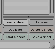
To add a new X-sheet to the scene, first enter the name for the new X-sheet to the Name: field, then click on the New X-sheet button below the X-sheets list.
With the Rename button you can rename the selected X-sheet to the name that given in the Name: field. You can duplicate the selected X-sheet with the Duplicate button, or you can delete it with the Delete X-sheet button.
The Load X-sheet and Save X-sheet buttons are usable to load or save the exposure sheet. The file format is a text, it's usability is very limited because most of the scene properties will be lost, only the contents of the X-sheet levels can be transferred.
If the scene has multiple X-sheets, before opening it, you need to select the X-sheet that you want to edit on the right side list. Or, you can open the scene by double clicking on the exposure sheet on the right side list.
If a scene is damaged and can not be loaded, or its latest version has been messed up, it is good to know that there is a penultimate saved version of the scene also on the disk. It is the version that was saved before the very last save.
You can load this safety backup with the Open the penultimate version item on the right button menu of the scenes list in the Scenes... window. It will open the penultimate version for editing.
There is another, more flexible option when you load the backup
directly as a file from the movie database folder. To do this, click
on the Load file button on the Scenes... window. In
the file load window enable the Filter
names option to see the names of the movies and scenes, otherwise
you can see only encoded filenames. Go to the folder of the Firka
program, and step into the “movies” subdirectory. On
the left side list of folders, you can see the names of the movies.
Step into the required movie. Now on the right side list you can see
the scenes of the selected movie as files. If a file is a backup copy,
there is a (PREVIOUS) label after its name. Find the required
scene and load it.
Sometimes Firka or your operating system crashes while you are editing a scene. Or the computer switches off, freezes, or restarts itself. For example, a fluctuation in the mains power can cause such a crash. It is recommended to use uninterrupted power supply (UPS) for the computer, but sometimes it still happens. It can be a pain if your works were unsaved. There is a chance to restore some unsaved picture data if the disk cache was in use. First, before you restart Firka, copy the contents of your cache folder to a separate folder on your disk. These are the remains of your unsaved data. Then start Firka, and open the scene you edited before the crash. There is a good chance that the opened scene is referring to the same cache filenames as before the crash. Now write over the contents of the cache folder with the saved copy. Then immediately save the scene into a new (external) ffs file, and exit the program. Start Firka again, load the saved scene and check the results. Sometimes this is working, sometimes not, or just partially, but maybe worth a try.
To load a scene from external file, click on the Load file button in the Scenes... window. Then the file loader window appears. In the window you can select multiple files together for loading. The program asks what to do with the loaded files.
If you selected only one file, then first it loads, then the program asks what do you want to do with it. Depending on whether or not the program recognizes the movie of the scene, the program may offers to insert the scene into its original movie where it belongs. It also offers to overwrite the currently selected scene in the scenes window, or to create a new scene.
But you can also choose an option by clicking on the Alone button to edit the scene by itself, without inserting it into the movie database. This is the safest solution, later you can insert the scene into the movie in a more controlled way, by using the Save as button on the exposure sheet window.
If you selected multiple files for loading, then these scenes will be inserted into the active movie. the program offers the choice to overwrite the scenes with the same name, or to save under new names (by adding a serial number) if two names collide. After this selection the scenes will be loaded into the movie.
When the scene finished, you may have to export it to some file format for additional processing. In animation this is most likely a serially numbered sequence of still image files. Firka handles many of these formats, for example jpeg, tga, bmp etc. Besides this you can use formats that contain the complete animation in some form, like avi and gif formats.
For more complex video exporting it is worth to export the frames in the best possible quality (probably with a lossless compression) into an image sequence, and then to use video encoding program to create the final file from the sequence. This also has the advantage that if the finished file is not of good quality, or you have to make multiple versions, you do not have to render the scene again, because it may be more time consuming than processing a picture sequence.
Additionally, if you archive the image sequence, you will have a very good master copy that you can later convert to anything.
In the program you can save the scenes by using the own file format of
Firka. This can be useful when archiving scenes, or making a backup
copy, or you want to send the scene to another Firka program user. The
name extension of the own format is “.ffs” (Firka
Format Scene).
If you want to save a single scene into external file, either in the program's own format or by rendering it into some other format, for example as an image sequence, first select the scene on the Scenes in the movie list, then click on the Save to file button. Then the file save window will appear where you can set the desired format and make the save.
In the Scenes... window, you can select multiple scenes at the same time from the list of scenes. Click on the first scene and move the mouse with pressed button over the scenes. Also you can select them one by one with the Ctrl+Left mouse button, or you can use the Shift+Left mouse button to select every scenes between the cursor and the clicked scene. A serial numbering becomes visible for the selected scenes.
After this click on the Save to file button below the list. If multiple scenes are selected, the program names the files that are being created by the name of the scenes. Therefore it asks you how to name them during the save. You can choose between the long names version and the 8+3 character, old DOS compatible version.
After this the file save window appears. Here you enter a name for a text log file, which will be placed next to the saved files and it will contain what file name was used for what scene name. After you entered the name and clicked on the Save button, the saving of the scenes will begin.
The exposure sheet contains what to render on the frames of the scene. When you already captured the drawings, sketched them or loaded them into the scene, you still need to fill the exposure sheet. Without this, the drawings will not appear in the animation. The exposure sheet is a table, whose rows correspond to the frames of the film and the columns of the list called levels (or layers). The levels contain the drawings, opaque parts of the higher levels covers the contents of the lower levels.
The displayed order of levels in the exposure sheet (from left to right or from right to left) can be set globally in the About window. The default is from left to right, so the leftmost column is the bottom one.
You can find some buttons in the top row of the exposure sheet window.
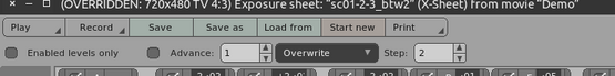
The Play button serves for playing the animation. Clicking on the button opens the player window, but it also has the Override playback format item in the menu, which opens the format override window, where you can override the field format and play speed of the movie for the currently edited exposure sheet.
The Record button opens a window where you can capture, create and edit pictures, sounds and movers. With the Save button you can overwrite the file of the scene which you are editing. With the Save as button you can save the scene under a different name in the active movie (the selected one in the main window), or you can export it to an external file. If some changes have not been saved, the program will warn you when you close the window and also offers you to save it.
If you want to keep the exposure sheet window open, and want to swap to another scene in the same window, you can use the Load from button, with which you can simply load another scene into the same window. The Start new button creates an empty, unnamed and unsaved new scene in the window.
With the Print button, you can print the exposure sheet in a text format. The Help button shows a help about the usage of the exposure sheet window. With the Close button you can close the window.
From the above, in the free version only the Save button exists, so that the scene can be overwritten in the internal database with the changes.
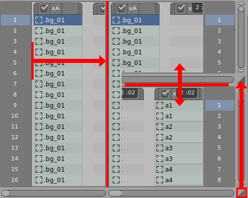
You can find a small sizer button at the right bottom corner of the exposure sheet, where the vertical and horizontal scrollbars meet. Click it, keep pressing the mouse button, and drag the button upwards. The exposure sheet splits into two horizontal views. These views show the same list, but two different parts of that. This way the exposure sheet can be divided into views. These views can disappear by resizing it with the sizer to the minimum. There is also a sizer bar at the left side to split the view into two vertical parts.
In the exposure sheet a cursor can be found. If the list is too big to fit in the window, it can be scrolled with the horizontal and vertical scrollbars. You can move it also if you drag the list with the mouse while pressing the Shift+Left mouse button, Middle mouse button, Shift+Middle mouse button. You can scroll only vertically by dragging the frame numbers in the side columns of the exposure sheet.
By pressing the F3 key, you can switch on or off the cursor row highlighting. It can help to align the contents of levels that are far apart.
The simplest way of writing the list in that you position the cursor to the desired place of the list, and you enter the name of the drawing with the keyboard. By pressing Return/Enter key the name will be written onto the list, and the cursor moves down. The Step: field at the upper row defines how many frames are to be written at the same time. There are four selectable inserting modes in a menu, which you can change also by using the Tab, Ctrl+I, Ctrl+Tab, Ctrl+Insert keys.
Overwrite
- overwrites the previous contents of the list,
Insert
- places the new content in front of the existing content which moves down
Sync (All) and Sync (Actives)
- these modes are similar to Insert but the other levels of the list are moved parallelly: Sync (All) moves all of them, and Sync (Actives) moves only the levels that are switched on.
With the keyboard you can move around in the list with the cursor moving buttons, just like in a text editor. If you put the cursor after the end of a level and enter something, it will fill the list from the end of the level to the cursor.
You can see the list of the pictures (the drawings captured with the camera) on the right side of the exposure sheet window. If the Thumbnails switch is enabled, the list shows the miniature version of the picture images. There are three buttons to the right of Thumbnails switch to set the sizes of these thumbnail pictures.
Under the list there are the Path: text input field for changing the listed folder and the Name: field, where you can enter an item name. This is an important parameter for some of the button commands.
You can select a series of items on the list to perform the same action on them together. For this, click on the first item and drag the mouse while pressing the mouse button until you selected all items you want. You can also select all of the items between the cursor and a clicked item on the list with the Ctrl+Left mouse button or Shift+Left mouse button combinations. You can select all items with the Ctrl+A key.
Over the list you can see three tab buttons. With these you can open the different groups of control elements.
Actions tab:
These are the basic operations for handling the items in the scene.
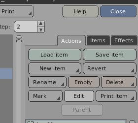
If you click on Load item button, you can load one or more items from files (picture, sound etc.). When selecting multiple files, the program asks whether to overwrite existing same names, or to automatically create new names in case of name conflicts. You can select from these choices in the requester window, with the Write over and Create new buttons. In this same window you can switch Leave out repetitions on, then the program will only load from the successive files those whose content differs from the preceding file. For animation image sequences, it is common that two or more successive frames contain the exact same picture. However, this loading mode can not detect when a picture is reused from another part of the sequence. The reason is, this way it's easier to fill the exposure sheet with the loaded pictures. After you filled the X-sheet, you can use the Unify identicals option of the right button menu on the items list, to remove all duplicated pictures.
In case of name conflict, the program overwrites the empty items even if the Create new was selected. An empty item has no type and does not contain any data, it is only a name placeholder. Still, you can enter it to the exposure sheet. To make an existing item empty before loading, you can use the Empty button. If you select a sequence of items on the right side list of the X-sheet window before loading, the program will overwrite them one by one, without question, even if they are not empty.
You can also load the items with the drag and drop function of your desktop. Use the mouse to drop the icon of the file onto the exposure sheet window.
If you want to save an item into a file, choose it and click Save item button. You can also select a series of items to save.
With the New item button, you can create empty, placeholder names, to fill the exposure sheet or to load items over them by using the Load item button. First enter the name for the item into the Item: field at the bottom right corner of the window, then click on the New item button. The created items will have no type and no data but later can be filled with a picture, sound or mover.
The New item button has also a menu. The Next and Next 10 modes first add the numeric value of the Advance: field to the item name before creating the new item. The Next 10 mode repeats this ten times, so it creates ten items at once. With New folder, you can create a new folder within the database of the scene.
The Revert button reverts the selected item from the last saved version of the scene. Each scene has two saved versions in the movie, the last and the penultimate version. You can choose which one you want to load by using the menu of the button.
The Rename button renames the item into the name in the Item: field. In the menu there are some variations of the command:
Keep numbering - attempts to keep the difference between numeric values of successive names,
Renumber - uses the value of the Advance: field to make equal increments in the numbering,
Dot prefix - keeps the names and inserts a dot ( .
) character in front of each name. Since the list of items is
ordered alphabetically, this places the selected items to the
beginning of the list.
The Empty button removes all the data and the type specification (picture or sound etc.) from the item. This is useful before loading a single item from file.
The Delete button deletes the selected items from the scene. You can delete a folder only if it's completely empty.
In the menu of the Delete button, you can select the Delete unused option, which deletes an item only if it's not referenced by the exposure sheet - any of the exposure sheets, if the scene has more than one. With this option you can clean up the unnecessary items from a scene. This also works on the contents of selected item folders.
In the same menu you can select the Unify identicals option as well, to remove the exactly same duplicates of the selected items. It searches for duplicates only within the selection. For example, if you import a sequence of drawings from another program, there can be held frames in the animation, two- or three-framed parts, repeats etc. With this option you can reduce these parts into single pictures. This also works on the contents of the selected item folders.
With the Mark menu you can add marks to the items. There are two kinds of these marks:
key mark - can indicate that the item is a key pose. Key drawings are usually the main motion poses in an animation, and inbetween drawings can be inserted between these keys to smooth the motion.
type marks - can show the origin working phase of the item. Just like a scene, an item can be marked as Layout, Rough animation, Inbetween etc. too.
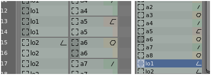
These markings are visible on the exposure sheet and also on the right side list of items. The key mark appears as a different background color on the left side, behind the icon or the thumbnail picture, and the type mark is an icon on the right.
Use the Edit button to start the same window as the Record button, to edit the selected item.
With the Print item button you can send the selected items to a printer. You can select the format of printing in the menu of the button.
If the list shows the contents of a sub-folder, the Parent button steps up one level in the directory hierarchy, just like in a filesystem. Changing the listed folder also changes the default folder for the level of the exposure sheet cursor. The list always shows the default folder for the cursor's exposure sheet level.
Items tab:
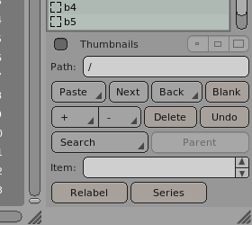
Use the Paste button to write the name of the Item: field onto the X-sheet from the exposure sheet cursor. The cursor moves down during this. In the menu of Paste, the By name numbers option inserts each element of a block as its length will be the difference in the numbering of successive names. This can be useful if the drawings are numbered accordingly to their required frame position in the exposure sheet. Selecting them on the right side list of the X-sheet window, then using the By name numbers menu item, each one will be pasted to as many frames as the difference in serial numbers, compared to the next name. Only the last item will be entered by the value of the Step: field, since there is no next name to compare.
You can write the next and previous elements of the list into the cursor by using the Next and Back buttons. In the menu of the Back button, the Block in reverse option reverts the order of the items on the selected part of the exposure sheet. The Mirror pictures marks the selected pictures as mirrored. The mirrored picture behaves as if the drawing was placed back side up onto the pegbar.
The Blank button writes blank frames. Blank frames are named with a blank text.
The + and - buttons extend or shrink the exposure sheet, you can change the timing of the animation this way. In the menu of these buttons there are additional options to change the timing (1-2-1-2... etc.). With the Shift pegbars option of the menu, you can replace the pegbar position of the selected pictures into a so-called “shifted peg” position. This means the picture is replaced parallel to the pegbar in such a way that one of the side peg holes is placed onto the other side peghole position.
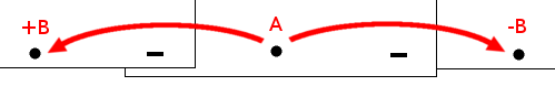
In this same menu with the Increment names and Decrement
names options, you can increment or decrement the serial
numbering of the names within the selected part of the exposure sheet.
This function uses the numeric value of the Advance: field to
add or subtract. For example, if you have two mover items with names
CAM1 and CAM2 , you can copy the X-sheet
motion entered for CAM1 into a different level, then you
can change every occurrences of CAM1 to CAM2
in the copy with this funtion, just increase the numeric
values by one, i.e. from 1 to 2.
You can delete the frame at the cursor by Delete button.
The Undo button is for reversing the previous modifications on the exposure sheet, multiple steps are stored. You can do the same from the keyboard with U, Esc, Ctrl+U, Ctrl+Z.
With the Search button you can search for the name entered into the Item: field. It can be an item name or an effect as well. If you simply click on the button, or use its Reveal on the side list menu option, the cursor of the right hand side list (items or effects) will jump to the name. You can use the Search in the X-sheet menu item to search in the entire exposure sheet from the cursor. The keyboard shortcut for this function is Ctrl+F. You can use the Search in the cursor's level menu item to search vertically below the X-sheet cursor in its level only.
The Parent button steps back with one level in the directory hierarchy. This button is the same as the one at Actions tab.
With the Relabel button you can change the letters at the beginning of the names in the selected range of the exposure sheet. During this, it keeps the numeric part and the end of the names. This way, for example you can copy the order of drawings in one level of the exposure sheet, and you can apply it in another level, with a different set of items.
The Series button fills the exposure sheet with a numbered sequence of names between the cursor and the content of the Item: field.
Effects tab:
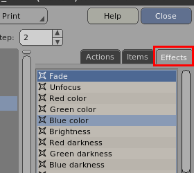
The buttons and their functions are similar to the buttons of the Items
tab. But the list contains the available effects instead of the
items. All effect names are beginning with two slash characters (
// ). The effects can have parameters. If you click on an
effect on the list, a window appears and you can select the affected
level group and the parameters for the
effect. With these parameters, the composed name of the effect appears
in the Item: field. After this, you can use the Paste
button to enter the effect into the exposure sheet. You can enter the
name and parameters of the effect manually into the X-sheet if it is
faster or more convenient.
The vertical columns of the exposure sheet are called levels. These levels include drawings, sounds and operations applied on them. The content of a higher level covers the content of the lower levels. This is a legacy from camera recording when the painted celluloid sheets were placed on top of each other under the camera. The bottom level can be the leftmost or the rightmost column of the list, by agreement (both versions are in use) and according to this, the levels are ordered from left to right or from right to left.
The exposure sheet has a cursor. You can enter the names into the X-sheet at this cursor. If you start typing a name from the keyboard, a text input field appears at the cursor. You can close the typed name with the Return/Enter key on the keyboard. The name is written to the number of frames specified by the Step: field, and the cursor goes down by the same number of frames in the level.
If you click near to the left edge of the cursor, you get a text input field where you can enter a comment for the cursor's frame. After you entered a text here, and leaved the input field, a small mark will appear on the exposure sheet. If you move the mouse over this mark, you can read the entered comment. To change the comment text, click on the mark twice and change the text in the input field. To delete the comment, erase the whole comment text with the keyboard.
Each level columns on the exposure sheet has a header part at the top of the column. You can enable or disable the playing of the level by using the checkbox on this header. The field next to the checkbox with a letter mark is an identifier name for the content of the level. The content of the level is independent from the level, you can redirect it to the content of another level, they can be unified clones of each other. The third field is the name of the level itself, it is defined to blank by default. If you click on it, you can enter a name for the level. It is just a remark without any means for the working of the program. You can hide the inactive levels from the exposure sheet with Enabled levels only switch.
By clicking on the two thin sizing bars at the sides of the header, you can use different mouse buttons to reach different functions:
Left mouse button
- by dragging with pressed button, you can adjust the gap between levels or level column width,
Right mouse button
- a menu appears with options to create a new level under or over the selected level,
Ctrl+Shift+Left mouse button, Ctrl+Right mouse button, Ctrl+Middle mouse button
- creates a new level. The new level gets the same settings as the selected level, its content will be a new empty column.
Shift+Right mouse button, Shift+Middle mouse button
- creates a duplicate of the level. The content of the new level will be unified with the selected level.
Ctrl+Shift+Right mouse button, Ctrl+Shift+Middle mouse button
- creates a new level with a default level group, pointing to the selected level. It is useful if you want to modify a level with an effect or mover.
Shift+Left mouse button, Middle mouse button
- swaps the order between the level and its neighbour. You can also drag the level to another location between the levels while holding down the button.
The level properties can be adjusted in the Level properties window, which you can bring up by clicking on the letter mark name on the level's header. You can read more about this in Chapter 6.7.
The named data, that can be entered to the X-sheet, for instance, pictures, sounds or mover paths, are called altogether by the program as items. The items are stored in the scenes in a directory structure similar to the filesystem of your computer. This does not necessarily mean that it is worth putting the data into sub-folders, most often it is enough if all the items are in the starting directory (root).
A default folder belongs to every exposure sheet level, where the
written names are searched for by the program. It is the last folder
viewed on the right side list, when the exposure sheet cursor was
inside the level. In the names, the separator character for folders is
the / (slash) symbol. If the path name begins with the
/ symbol, this indicates an absolute path, otherwise the
path is relative to the default folder of the current level.
For example: /rough/first/A1 is an absolute path of the
location of A1 drawing in the folder. To enter this
A1 into a level, A1 is enough if /rough/first
is the default folder for the current level. If you are, for
example in the rough subdirectory, the correct relative
name is first/A1 .
For the effects, which are not parts of this directory structure, the
names start with // (double slash) characters.
The most important data type in an animation software is the picture. To put pictures into the items database, use the window you can open with the Record button of the exposure sheet window. In this window, if the Pictures tab is active at the top right corner, you can capture pictures with camera or scanner in the Record mode, which you can select with the button right below the tabs at the top right corner. At this same place you can select the Paint mode as well, where the pictures can be painted and redrawn.
In addition, pictures can be loaded in a variety of formats from files. This way Firka can be used together with other (painter) programs to make the animation.
The geometry of the pictures can be characterized by three parameters:
- width (in pixels),
- height (in pixels),
- aspect ratio (for the entire picture).
So the aspect ratio is not of the pixel, but of the picture itself. The advantage of this solution is that, for example the pixel resolution can be changed without changing the size and shape of the picture, if its geometrical aspect ratio remains the same. The Firka program does not care about the scanning and printing resolution of the pictures (DPI), it does not take into account in any way.
There can be any number of sublayers within a picture. These sublayers should not be confused with the levels of the exposure sheet: these are located inside the picture, together they form the picture. Each sublayer can be in one of the eight named type. In the levels of the exposure sheet, these types can be enabled and disabled individually. These sublayers help to keep the logically related visual information (outline, paint, masks) together.
The naming of these types is only helps to remember them easier. Because the sublayers are functionally identical, they may also be used freely for purposes other than the function suggested by the name. Usually a picture contains only at most one piece from each of the sublayer types, but the program can handle multiple pieces if necessary.
The sublayers, from top to bottom:
1. Generic - General purpose layer, for example you can capture the line test into this layer,
2. Effect - For effects covering the outline, for example self shadow,
3. Outline - Outline drawings,
4. Paint - Sublayer of the painting, so the paint can flow under the outline,
5. Shadow - For cast shadows, behind the paint,
6. Mask - For masks, moving together with the drawing,
7. Texture - For textures, projected onto the character,
8. Spare - General purpose spare sublayer.
In a sublayer the true-color RGB pixels (8 bits per component) can be mixed with indexed palette color pixels, from up to 256 palettes, each with a maximum of 256 colors - so 65536 paletta colors. The pixels can contain a 255 level transparency, and there is a particular “transparent color” too. The program stores the pictures with a lossless compression within the scene.
When entering to the exposure sheet, after the name of the picture and
a / (slash) character, plus-minus B ,
C , D can be given as a parameter for
shifted peg positions. The shifted peg is easy to do with manual
drawing, so common for scenes with long pan backgrounds. The positive
direction is to the left from the default pegbar, and the negative is
to the right from it. For example:
a1/+B
a1/-D
The drawing can be mirrored relative to its pegbar the similar way like
when it was placed onto the same pegbar back side up. The axis of the
mirror is perpendicular to the line of the pegholes and goes through
the center of the middle peghole. The sign of the mirror is R
, which must come right after the shifted peg or right after
the / mark if there is no peg shift:
a1/R
a1/+BR
In the exposure sheet, for the pictures you can enter a combination of 1..5 sublayers. In this case the program plays only the given sublayers and ignores the settings in the level properties. The 6,7,8 sublayers cannot be handled this way, they can always be disabled for the X-sheet level. If there is a shifted pegbar or mirror in the name, the combination should come after these, separated with a space. For example:
a1/25
a1/-C 134
a1/+BR 3
The exposure sheet is able to contain sound information too. Similarly to the pictures, you can enter any number of sounds parallelly to the levels of the exposure sheet, and the summary of these make the sound of the scene. The sounds are stored in PCM format without compression, in 8 or 16 bits, mono or stereo format, according to the format of the original sound record. There can be any sampling frequency.
The sounds are represented on the exposure sheet with their name and the shape of their waveform. It is also possible to put the sound waveform over the picture in the player window.
A sound can contain dialog breaking down data. The breaking down helps the animator, to be able to move the mouth of the character frame-by-frame based on the pre-recorded speech (dialog) sound. This called also as lip-sync animation.
A sound can contain two breaking down text layers, named Phonemes and Words. You can fill these in the sound recording window, by assigning text labels to certain positions in the sound. If the rows are not visible below the sound waveform, zoom into the sound until they become visible. The Phonemes row should contain one or two letter phonemes for the individual frames, and the Words row should be the literal text, divided to words or syllables.
Since the breaking down positions are connected to the internal timeline of the sound, their position will still be correct if the movie's frame rate shoud be changed due to a format change.
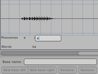
This is an example of breaking down (Original dialog: “firka”
):
Phonemes : f i i r k a a a
Words : fir- ka
The program shows the contents of the Phonemes layer in the exposure sheet. You can see the contents of the Words row as well, in the tooltips of the sound items, starting from the selected frame in the exposure sheet. This help appears automatically if the mouse pointer remains still over the sound for enough time, but you can display it immediately by pressing Ctrl+Shift+Left mouse button, Shift+Right mouse button.
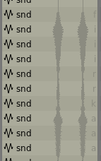
Each sound can contain at most 255 base tags. The bases are marked with names, and they can represent positions in the sound. The position of the base can be any, and later it can be changed. Like with the breaking down, you can edit these in the sound recording window.
In the exposure sheet, after the name of the sound, after a /
(slash) character, you can enter the name of a base, in this
case the playing of the sound starts at the position of the base
instead of its beginning:
sound1/base1
It is also possible to specify a frame offset, which will be added to
the starting point of the sound. This shifts the starting position of
the sound by a time distance, measured in frames. You can specify this
offset with numbers, and optionally a # character after
them. The two methods are similar. If there is also a base, add it
after the offset, after a / separator character:
sound1/25#/base1
sound1/25/base1
sound1/13#
sound1/13
Bases should not be named with only numeric characters because it makes
the interpretation of the entered parameters difficult. The entered
name is first searched as a base name, and if there is no such name,
then it will be used as a frame offset. Use of the #
after the frame offset can make things more clear.
In the exposure sheet, when you select a block inside a sound and paste it back into the list, the offset of the sound will be automatically corrected so that the inserted part will be the same as the selected part of the original sound. This way you can easily cut parts from the sound and insert them into the required place in the exposure sheet.
Movers are items stored under names, like pictures or sounds. By entering its name into the X-sheet, it can change the position of other levels. In the X-sheet the mover affects the levels of the selected level group, just like how effects do. You can read more about the level groups in Chapter 6.7.3.
A mover can have at most 16 key positions, marked with letters from A to P. These are the key points of the motion path. On the X-sheet, you can make transitions between these points in any combinations.
If the Items tab is active in the X-sheet window and you click on a mover in the right side list, a settings window appears, to set the parameters for entering the mover into the exposure sheet.
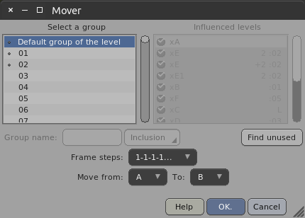
If you want to use the default group of the level that will contain the mover, just leave the list selection on the Default group of the level option. Normally it is better to use a separate X-sheet level for a mover and to use the level's default level group to select the affected levels.
With the two lists and the buttons below them you can edit the level groups. The functions of these are similar to the matching controls of the level groups window, and you can read about them also in Chapter 6.7.3.
It can be a problem for movers when the animation moves not frame by frame, for example it changes on every second frame, or alternating by one-two frames. In this case various unwanted artifacts can happen, like flickering.
This is why it is useful the movers can be moved by multiple frame steps too. In this case for exampe with a two frames step, on every second frame the program repeats the position of the previous frame instead of using the current position. This has variations according to the widely used framing methods, which can be selected with the menu next to the Frame steps: label:
1-1-1-1... - step by single frame, every frames have a new position,
2-2-2-2... - step by two frames, the position changes on every second frame,
1-2-1-2... - alternate step by one and two frames,
etc.
The start and end points of the path can be set with the menus of Move from: and To:.
After you prepared the mover, click on the OK. button. The name to enter into the X-sheet will be written into the Item: input field on the exposure sheet window. This has to be pasted into one of the levels of the exposure sheet by the Paste button.
If you want to write the mover into the exposure sheet directly, you can use this format:
name[/keypoints[/framing]] [level group]
The key points can be entered after a / (slash) character
after the name of the mover item. The AB or A-B
format means a transition from key position A to
key position B . If only B was given, the
mover will remain still on the B key position. In case
of no key position, the A-B movement is the default.
Examples:
cam
cam/AB
cam/G-F
The [framing] parameter should be entered into the name after the key
positions, separated by an additional / (slash)
character:
If there is nothing, the motion is single framed:
1 2 3 4 5 6 7 8 9
/2 two framed motion:
1 1 3 3 5 5 7 7 9
/3 three framed motion:
1 1 1 4 4 4 7 7 7
/4 four framed motion:
1 1 1 1 5 5 5 5 9
/12 alternating one and two framed, the first step is one
framed:
1 2 2 3 5 5 7 8 8
/23 alternating two and three framed, the first step is
two framed:
1 1 3 3 3 6 6 8 8
/34 alternating three and four framed, the first step is
three framed:
1 1 1 4 4 4 4 8 8
/45 alternating four and five framed, the first step is
four framed:
1 1 1 1 5 5 5 5 5
The program shows the boundaries of the frame steps in the exposure sheet with pale color horizontal separator lines.
The name of the moved level group can be given to the end of the name
of the mover, separated by a space character. Not giving this, or
entering the All keyword or the 00 number
means that the default group of the level containing the mover will
determine which levels to be moved. Entering the level group into a
name is recommended only in justified cases, it is more convenient to
set this default level group at the level
properties.
Some other examples for a mover definiton:
cam - moves between A and B
key points, by single frame step,
cam/F - remains still in the F position,
cam/DC/2 - moves from D to C
point, by two frames step,
cam/EO/34 01 - moves between E and O
, by alternating three and four frames steps, moving the levels
of the 01 level group.
Various optical effects, lens, waves caused by water or heat, torsions can be made with the picture morph items. These are displacement maps, each pixel is a vector, points to another pixel of the image, and the copied colors from these locations make up the result. With this any kind of distortion can be possible. You can imagine its operation as a pitted glass plate under the camera. The distorted layers are visible only within the glass plate, distorted by it.
The geometry of morph items is the same as pictures, and also can be handled similarly: morphs can be put on pegbars and also can be moved by movers. The displacement map is a pixel surface, which has width, height and aspect ratio. It does not use color mixing, every pixel points to a specific other pixel within the surface and it will get only the color of the other single pixel. Unlike a picture, a morph has no sublayers, a morph item contains only one displacement map.
Because distortion usually means enlargement of some picture parts, it is worth to think what is the right resolution for initial pictures and distortion to achieve the desired result. This may eventually be higher than what is otherwise used in the movie.
In the program, distortions can be created in the drawing window, by using the Morph button, and then by storing the created distortion under a given name, with the menu of the same button.
For the morph, similarly to the effects, a level group should be given, the layers of which will be affected. If there is nothing specified, the program will use the default level group of the morph's level.
When entering to the exposure sheet, after the name of the morph and a
/ (slash) character, plus-minus B , C
, D can be given as a parameter for shifted peg
positions, just like with pictures:
m1/+B
m1/-D
The morph can be mirrored relative to its pegbar the similar way like
when it was placed onto the same pegbar back side up. The axis of the
mirror is perpendicular to the line of the pegholes and goes through
the center of the middle peghole. The sign of the mirror is R
, which must come right after the shifted peg or right after
the / mark if there is no peg shift:
m1/R
m1/+BR
If it is necessary, the level group for which the distorion will have effect can be entered to the name of the distortion. It is usually not worth to specify it this way, but instead it is better to use a separate X-sheet level for a morph and to use the level's default level group to select the affected levels. If there is a pegs position or mirroring in the name, the level group can be entered after them, with a space character separator, for example:
m1/01
m1/-C grp1
m1/+BR 03
The effect is a modifier for pictures or sounds. You have several effect types to change some properties, like transparency, focus (blur) or color components. For sounds you can change the volume, for example. An effect modify a particular combination of levels, defined by the level group.
You can see the list of available effects if you select the Effects tab in the exposure sheet window. Then the available effects appear in the list on the right side.
To create an effect, for example an unfocus, click on the Unfocus entry of the list. A new window appears where you can select a level group. A level group is a named combination of levels. You can read more about the level groups in Chapter 6.7.3.
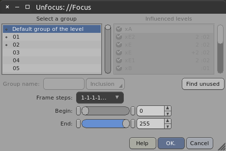
If you want to use the default group for the level you enter the effect command, just leave the list selection on the Default group of the level option. Normally it is better to use a separate X-sheet level for an effect and to use the level's default level group to select the affected levels.
With the two lists and the buttons below them you can edit the level groups. The functions of these are similar to the matching controls of the level groups window, and you can read about them also in Chapter 6.7.3.
At the bottom of the window you can see some controls, where you can adjust the effect. Depending on the effect type there are some variations but most of the effects has the same parameters.
The Frame steps: menu selects the changing steps for the effect's value. You can use one frame steps or two frames steps. With the Begin: and End: sliders you can set the strength of the effect for its first and for its last frame. The values are working on the 0-255 range. For example you can make a fade in if the value starts at 0 (full transparent) and ends at 255 (full opaque). By reverse, you can make a fade out if it starts at 255 and ends at 0.
The start value belongs to the first frame of the effect, but the end value belongs to the next frame after the last frame of the effect. So the last frame will be one frame before the end value. This logic is common in Firka, movers work the same way, the reason behind this is to be able to make uninterrupted, continuous changes.
After you prepared your effect, click OK. button. The effect command will be formed and written into the Item: input field on the exposure sheet window. This has to be pasted into one of the levels of the exposure sheet by the Paste button.
If you want to write the effect into the exposure sheet with the keyboard, you can use this format:
//effect [range][/2] [level group]
The effect name always begins with // (two slash
characters) then continued with the name and the parameters of the
effect. An item name never begins with two slashes in the program.
The [range] can be:
number-number
- Write a minus sign between start and end numbers, i.e. 10-150.
number
- In this case the start and end are the same, the effect keeps a constant value to the end.
in and out
- the in keyword subtitutes 0-255, and out ,
subtitutes 255-0, these are the most common begin-end transitions.
If there is no [range] parameter given, the program
assumes it as 0-255.
Right after the [range] parameter, a /2
option can be added, which defines a two frames step. This means,
every second frame of the effect will repeat the value of the previous
frame instead of using its own value. For example, if the value of the
effect looks like this on the frames without the /2
option:
0 1 2 3 4 5 6 7 8
Then the same when /2 entered:
0 0 2 2 4 4 6 6 8
The [level group] is the name of the level combination,
i.e. the name of a level group or its hexadecimal serial number (16
based digits are: 0-9 and A-F). Not giving this, or entering the
All keyword or the 00 number means the
level group is not defined in the effect, and the effect will modify
the default group of the effect's level, which defined in the level
properties.
Examples of effect definitions:
//focus
- Unfocus transition between 0 and 255, by one frame step, it will affect the default level group of the effect's level, which defined in the level properties.
//fade in/2
- Fade between 0 and 255, two frames step, it will affect the default level group of the effect's level.
//red 100-30 01
- Transition between 100 and 30, one frame step, it will affect the levels selected by the level group named “01”.
//red 100-30/2 01
- Transition between 100 and 30, two frames step, it will affect the levels selected by the level group named “01”.
For switch type effects, if there are any, you can define a letter
combination parameter, entered to the place of the [range]
in the format.
The effect names can be entered as one or two characters long abbreviations.
The effect types:
Fade - transparency of the level
//fade [range]
Abbreviations: //fa //f
Unfocus - unsharpness (blur) of the level
//focus [range]
Abbreviation: //fo
Red color - mix red color component with 100% red
//red [range]
Abbreviation: //r
Green color - mix green color component with 100% green
//green [range]
Abbreviation: //g
Blue color - mix blue color component with 100% blue
//blue [range]
Abbreviation: //b
Brightness - mix color components with white
//bright [range]
Abbreviation: //br
Red darkness - mix red color component with 0% red
//darkred [range]
Abbreviation: //dr
Green darkness - mix green color component with 0% green
//darkgreen [range]
Abbreviation: //dg
Blue darkness - mix blue color component with 0% blue
//darkblue [range]
Abbreviation: //db
Darkness - mix color components with black
//dark [range]
Abbreviations: //da //d
Hue - color wheel hue shift
//hue [range]
Abbreviation: //h
Towards blue (0..low values) or towards red (high values..255).
Hue cut point - cut point for hue shifting
//hue_cut [range]
Abbreviation: //hc
Use this together with the Hue effect. You can set the point where the long wavelength (red) colors connect to the short wavelength (blue and violet) colors on the color wheel. If it has a nonzero value, the program restricts the overflowing during the Hue operation for a physically correct color shifting. Use 0..127 for red shifting and 128..255 for blue shifting. If this value is not given or zero, the color wheel is cyclic so the long wavelength colors can overflow into the short vavelength range and vice versa.
Saturation - color saturation
//saturation [range]
Abbreviations: //sa //s
From grayscale (0) to unchanged (128) and to oversaturated (255).
Amplify color value - amplification of color
//amplify [multiplier]
Abbreviation: //am
Multiply R,G,B color component values with the given value (0..255).
Amplify Alpha - amplification of opacity
//ampalpha [multiplier]
Abbreviation: //aa
For example, blurring can give very pale, transparent results. In this case, you can make the result more visible by multiplying the alpha values. This is specially useful with final quality rendering, because 16-bit calculation gives enough accuracy to amplify low values, without visible quality loss.
Alpha weight - the contrast of the transparency
//alpha [range]
Abbreviations: //al //a
Alpha threshold - fully opaque above the given alpha value
//threshold [range]
Abbreviations: //tr //t
Threshold padding - fully transparent below the given alpha value
//thres_pad [range]
Abbreviation: //tp
The value of Threshold padding maps to the range between 0 and
the value of Alpha threshold (or between 0 and 255 if there is
no //threshold effect). Its 0 value maps to the high end
value, and its 255 value maps to zero, ie. it has no effect. The alpha
range defined this way then will be streched to the full range of
transparency. Transparency values below this range will be 100%
transparent (alpha = 0), and values above it will be 100% opaque
(alpha = 255).
Hard cut Alpha - hard transparency
//hard [range]
Abbreviations: //ha
It converts alpha values below the given value to 100% transparent (alpha = 0) and values above the given value to 100% opaque (alpha = 255).
Cross-fade - multi-pass crossfade, double exposition
//cross [range]
Abbreviations: //cr //c
It renders the scene in multiple passes, the selected levels in the
effect's level group are rendered only in the pass that belongs to the
effect. This does not only apply to levels that contain picture, but
also apply to morphs and movers. The levels that do not belong to any
crossfade groups, or that contain effects, are processed in all
rendering passes. The order of the passes is determined by the order
of the level groups' serial numbers and not by the location of the Cross-fade
effect in the exposure sheet. The first pass starts with the
effect that has the lowest group number (01, 02 etc.), then the second
lowest comes and so on. The result of a pass is mixed to the image in
proportion to the parameter of its //cross effect. If
the value is 0, it does not change the image, while 255 entirely
replaces it.
Repeat cross-fade - subframe motion interpolation (blur) in a cross-fade pass
//multi [range]
Abbreviations: //mu //m
It repeats the cross-fade pass ( //cross ) of the same
level group. The value of the effect is the number of the repeated
passes. If there are time fraction ( //fraction )
effects, their values are interpolated during the passes, between 0
and the value of the //fraction effect. The repeat value
takes effect only for the final quality rendering, in draft modes the
program renders only the two side points. Be careful when setting too
high repeat values, because each pass requires a render for the entire
scene, so the rendering time could become very long.
Sub-frame time fraction - time offset within a frame for movers
//fraction [range]
Abbreviation: //fr
With this effect you can place the motion position between the actual
and the next frame. You should apply this effect on mover levels. It
defines a time offset within the frame's time interval. The repeat
cross-fade effect ( //multi ) interpolates this time
offset between zero and the given value during the repeated render
passes. You can use the cross-fade, the repeat cross-fade and the
sub-frame time fraction ( //cross , //multi ,
//fraction ) effects together to make motion blur
effects. In this case the time fraction behaves like the shutter angle
of a film camera. If the value is higher, the blur is longer along the
motion path. To create a motion blur effect, set the //cross
and //multi effects to the same level group. THE
FOLLOWING IS IMPORTANT! You not only include the picture (and mask)
levels to be blurred into the level group, but also include the mover
levels that are responsible for the motion blurring. The //fraction
effect should be applied to these mover levels. You can use
the same level group for that, since it already contains the required
mover levels. Or, if you want to use different shutter angle values
separately for these mover levels, you can set other groups and
multiple //fraction effects as well.
Audio volume - the volume of both audio channels
//volume [range]
Abbreviations: //vo //v
The /2 option does not mean two frames steps here, but it
multiplies the volume by two. Without it, the volume can be set from
0% (0) to 100% (255), but if you specify the /2 switch,
the maximum value will be 200% (amplification).
Audio left - the volume of the left audio channel only
//left [range]
Abbreviation: //lt
Audio right - the volume of the right audio channel only,
//right [range]
Abbreviation: //rt
Ease other effects - makes the transient curve of other effects smooth
//ease [range]
Abbreviations: //ea //e
The given range for an effect defines a value transition through frames. This value transition can be calculated with linear or ease in/out (smooth) interpolation. The default, because of historical reasons, is linear. You can apply this effect on other effected levels or on the levels of other effects. Zero value means the other effect will be calculated with ease in/out and 255 means the original default linear mode. Values in between means interpolation between these two modes.
Quick unfocus - switch: faster unfocus calculations
//quickfocus
Abbreviations: //qf //q
The selected levels will use a faster, but inferior quality linear filter blurring instead of Gaussian blur. It has effect only for the final quality rendering.
Linear space unfocus - switch: uses linear color space for unfocus effects
//linearfocus
Abbreviations: //lf //l
Fine unfocus - switch: fine unfocus effects
//finefocus [/248]
Abbreviation: //ff
Sometimes the resolution of the unfocus effect value is not enough for
fine unfocusing near the maximum value (255). This specially happens
with high resolution images and large field formats. With this effect
modifier, you can make lighter unfocus effects. The /2
option (or no option) multiplies the value of the unfocus effect by 2
in the calculations. This means the highest unfocused value without
//finefocus , which is 254, will be the same as 127 with
//finefocus . All values above 127 will be sharper than
the sharpest possible unfocused value without //finefocus
. If this precision is not enough, you can use the /4
or /8 options to make things even sharper. This
works on all kind of unfocusing, for example, on pictures used as
unfocus masks, too. To achieve the same unfocus effect with different
//finefocus options, just divide the effect value with
the applied //finefocus option value. For example:
//focus 200 is equivalent
to:
//focus 100 with //finefocus (or //finefocus/2
, as they are the same), or
//focus 50 with //finefocus/4 , or
//focus 25 with //finefocus/8 .Inverted - switch: inverts selected channels of the picture
//invert [ARGB]
Abbreviations: //in //i
By giving the A , R , G , B
letters (Alpha, Red, Green, Blue), any combination of the
transparency and the color channels can be inverted. If nothing is
specified, it is equivalent to RGB .
Alpha from RGB - switch: converts color channel to transparency
//from [YRGB]
Abbreviation: //fr
Calculates Y (grayscale brightness), R ,
G , B or a combination of these into
transparency. If nothing is specified, it is equivalent to Y
.
Compose levels together - switch: composes multiple levels together as a single level:
//comp [+-]
Abbreviation: //co
This effect separately composes the intermediate X-sheet levels between
the actual and the previous //comp effect, over a
transparent background. For the first occurence of //comp
, it composes all of the preceding levels, up from the bottom.
The result will appear as the own content of the effect's level,
instead of the merged levels. The picture size will match to the
rendering field. You can move, morph, mask and effect the merged
picture. This effect type ignores the level group settings.
With the //comp + option (with a plus sign), you can add
the upcoming levels to the current composition as a nested
composition. Also the //comp + represents the levels
preceding it.
The //comp - (with a minus sign) closes and represents
the content of the nested composition. A //comp without
+ or - works within the current nesting
level. Embedded nesting is possible with a maximum depth of four.
Repeat the field content - switch: duplicates the already rendered picture as a level
//repeat
Abbreviation: //re
During rendering, this effect gives a copy of the already rendered
picture content up to the effect's level, as the own content of the
effect's level. The result will be blended over the existing picture.
The picture will match to the image field and its background will be
either transparent, opaque or checkered, depending on the selected
background of the rendering. This effect is specially useful when you
want to merge the same picture content multiple times, like double
vision or kaleidoscope etc. If you need a transparent background, you
can put the level of the //repeat effect, together with
its doubled levels into a separately rendered level range by using the
//comp effect.
Render the group to file - switch: renders the levels of the level group to a separate file
//file [/A]
Abbreviation: //fi
This effect applies only while saving the scene into an image sequence
(jpg, tga...). Otherwise it does nothing. With this effect, you can
render multiple subsets of the scene levels into separate image
sequences. For example, you can render each characters, their shadows
etc. separately, for later compositing. It means that when you save
the scene, you dont need to make these passes manually. If the scene
contains one or more of this effect on a frame, the program creates
and uses subfolders for each of them, named by the referred level
group names. It renders only the levels contained by the level group
of the effect. Enter the //file effect for every frames
you want to render this way. Also rename the used level groups to the
required folder names. The /A option switches the Keep
transparency setting on for the actual render pass.
Masking means hiding some parts of the visible level contents. These hidden parts become partially or completely transparent. Masks are regular pictures, and the type of the containing level determines how the other layers are masked. For masking, only the transparency matters, the color of the mask picture is not used.
For example there is a background level and a figure level in front of it, but some background elements are actually covering the figure. In this case, you can make the covering element as a separated picture, and put it to a level above the figure. This is called a background overlay. But sometimes this solution can be difficult, specially if only some parts of the figure is covered, for example the background element should be between the body and the arm. So instead of modifying the background, you can make a mask to hide exactly the covered parts of the figure. These hidden parts will be transparent, so the background behind them will be seen, giving the effect of being in front of the figure.
There are multiple mask level types, to mask with the transparency (positive mask) or with the inverse transparency (negative mask), and the masks can be merged together before the actual masking (union mask). Mask levels do not affect each other, there is no masked mask option. You can apply multiple masks on a level, and the order of the mask levels in the X-sheet determines the order of the masking operations. You can read more about the various mask level types in Chapter 6.7.2.
Additionally, a self-mask can be set for a level at the properties of the level, in this case a picture is masked by its own sublayer, according to the selected mode. This option is independent from the other masking modes, and it can be used even for mask level contents.
To get the captured drawings to move, you need to fill the exposure sheet. This lets you specify what to project on the frames of the scene.
There are multiple ways to fill the exposure sheet. The list entries or motion steps are in text format and occupy one or more consecutive frames (rows) in a level.
In a level there can be only one entry in a frame. So, for example if
two pictures overlap in time because of a crossfade, the level must be
separated to two levels. Where one drawing fades to another, the two
drawings must be placed to two separated levels, overlapped for the
time range of the fade, and with two //fade
effects, one level must be faded out and the
another must be faded in. For painted, filled drawings, it is better
to use the //cross crossfade effect.
Usually the list will be filled from top to bottom, level by level. In the list there is a cursor, which shows the entering position. With the left button of the mouse you can replace this cursor anywhere in the list. If the X-sheet is active, as indicated by a change in the frame of the list, the cursor buttons of the keyboard are also usable to move the cursor.
The projecting length of the list is the same as the length of the longest level (the levels that switched off from projection are also count). The levels don't need to have the same length: if a level is shorter than the projecting length, it is the same as if it were filled with blank frames at the end.
The full content of the list often bigger than the area shown in the window. With the middle button of the mouse, you can scroll the list in the view area, and also you can use the scrollbars at the sides of the list to change the position of the displayed part.
When you enter something after the end of a level, the list will be filled with the entered name from the end of the level to the position where the entering happened. This feature is useful to enter long still motion steps, such as backgrounds.
Because of the simple text format, the list can be filled easily with the keyboard as well. There are people who prefer to use mouse over keyboard, so the list also can be filled by using the right side list of the items and the buttons belonging to it. If the right side list is active, you can effectively use the keyboard as well to enter, specially if the drawings are not evenly numbered, i.e. for rough or layout scenes.
You can find the full list of usable key combinations for the X-sheet window in the Appendix A.1.
The following keys are usable in the exposure sheet window, regardless of whether the exposure sheet field is active or not:
Tab, Ctrl+I, Insert
changing the insert mode to the next mode, cyclically.
Ctrl+Tab, Ctrl+Insert
reset the insert mode to the default, Overwrite.
Ctrl+Space
switching on and off the automatical name advancing, the status of which is indicated by the Advance: switch at the top part of the window. In automatical advance mode the value of the Advance: field is always added to the serial number in the name after entering, therefore you can enter an ascending or descending numbered sequences of names by just repeated pressing the Return/Enter key.
F8
increase the entering step value (Step: field),
F7
decrease tge entering step value (Step: field),
F11
opening the player window, similar to pressing the Play button.
F2
opening the record window, similar to pressing the Record button.
F3
switches on and off the highlighting of the cursor's row. Marking the row makes easier to sync the motion steps belonging to the same frame on levels far away from each other.
For editing the exposure sheet from the keyboard, you should activate it by clicking on it with the left mouse button. This also places the cursor to the clicked position. When the X-sheet field is active, you can use the cursor control keys on the keyboard to move the cursor:
Left, Up, Right, Down
step the cursor by frames and from level to level,
PgDn, PgUp
jump the cursor to the start of the next motion step, or to the end of previous,
Home, Shift+Home, End, Shift+End
jump the cursor to the start or end of the level,
The following keys can be used for editing the list:
Delete, Ctrl+D
delete the frame right above the cursor according to the current insert mode,
Ctrl+Return/Enter
step into the comment entering mode. You can assign a comment to any frame of any levels, and after the entering, a small marker shows the position of the comment. By moving the mouse pointer over the marker, the program shows the text of the comment in a bubble. You can delete the comment by emptying its text.
Esc, Ctrl+Z
undoing the last list editing operation.
Return/Enter, Backspace, letters, numbers and signs
If you press the Return/Enter key, or a key that inserts or deletes something when entering a text, the programs steps into the name entering mode. This is indicated by an input field in the cursor's location. The text input field has its own, narrow stripe cursor. Next to the text field there are two small buttons (up and down), to increase or decrease the number in the name, by using the mouse.
During name entering the meaning of horizontal arrow keys becomes different, in this case they move the text cursor. The vertical arrow keys still serve to move the cursor in the X-sheet, so you can exit from the text entering mode with these keys. You can also close the text entering by clicking elsewhere with the mouse.
When exiting from the text entering, or by pressing the Return/Enter key, the program evaluates the contents of the text field and inserts the name into the list.
Pressing the Return/Enter key enters frames into the list, equal to the value of Step: field, and the X-sheet cursor moves down the same number of frames, while the cursor remains in the text entering mode.
Text entering can be cancelled with the Esc key, in this case the list content remain unchanged.
If you click on the separator line between two names (motion steps) on the exposure sheet, you can drag the selected edge up and down, while changing the length of the motion step right above the selected edge. The level content below will move together during this, and in Sync (All) and Sync (Actives) modes, the other levels will follow the resizing, too. You cannot delete the entire motion step this way, it will remain there for at least one frame in length. If you drag downwards the top edge of the first frame this way, you can insert empty frames before the level content.
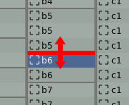
On the right side of the X-sheet window there is the list of items. This shows a folder of the item database of the scene, the one given in the Path: field. By double-clicking on the names in this list you can enter them into the exposure sheet. When the list of items is the active element in the window, you can use an alternative keyboard entering mode too.
There are three buttons above the list of the items. The right side part of the window can perform various functions with these:
Actions tab:
By clicking on this tab, buttons appears above the list field, mainly to edit the contents of the items list and for operations performed on items. These functions are not related to the filling of the X-sheet and you can read more about them in Chapter 6.
Items and Effects tabs:
With these two buttons you can choose between the list of items or the list of available effects.
The buttons below the list are the same in both cases:
Paste
- entering the name in Item: field to the exposure sheet
cursor, the entered number of frames is determined by the Step:
field, while the cursor moves down the same number of frames. If
the Item: field contains a single / character,
it enters the contents of the last selected block. If there is a
block selected on the X-sheet, it overwrites
the contents of the block. By holding the button pressed, it repeats
the entering.
Next
- the cursor of the items list moves forwards by one, it enters the name at the cursor into the Item: field, then enters it to the X-sheet the same way as with the Paste button. By holding the button pressed, it repeats the entering while stepping forwards on the list of the items.
Back
- the cursor of the items list moves backwards by one, it enters the name at the cursor into the Item: field, then enters it to the X-sheet the same way as with the Paste button. By holding the button pressed, it repeats the entering while stepping backwards on the list of the items.
This button has also an optional menu, which you can bring it up if you move the mouse pointer away from the Back button while holding down the button on the mouse. The Block in reverse menu item turns the order of the motion steps of the selected block backwards, and the Mirror pictures menu item mirrors the pictures relative to their pegs. If there is no block selected, these menu operations affects the entire level of the cursor.
Blank
- enter empty (blank) frames into the X-sheet. If there is a block selected, it fills the block with empty frames.
+ and -
- the motion steps in the selected block, or when there is no block, the motion step at the cursor will be increased or decreased in its frame length. Each motion steps, i.e. contingent parts of the list are counted separately, with the help of this you can convert a one-framed sequence into two-framed, three-framed etc. and vice versa. Holding the buttons pressed repeats the operation. For example, if you selected:
a1 a1 a2 a2 a3 a3
and press the + button, the result will be:
a1 a1 a1 a2 a2 a2 a3 a3 a3
The buttons have optional menus, which you can bring it up if you move the mouse pointer away from the button while holding down the button on the mouse. From the menu you apply som commonly used framings (alternating one-two framed, etc.), and with the Shift pegbars menu item you can translate the pictures by whole pegbar distances into shifted pegs positions. This latter can be applied by clicking on the button with the Ctrl+Left mouse button, Middle mouse button too, and if there is no block selected, it will modify the entire level of the cursor.
Delete
- delete the contents of the block according to the current insert mode. If there is no block selected, it deletes the frame right above the cursor. From the keyboard, use the Delete, Ctrl+D key for the same.
Undo
- undoing the last list editing operation. Repeat pressing it to undo multiple editing steps. You can also use the Esc, Ctrl+Z key on the keyboard for this.
Parent
- not for editing, but to step back to the parent folder of the displayed item folder, defined by the Path: field. So it steps up one level in the directory structure. It is only usable when the list of items shows a sub-folder.
The Path: shows the access path of the folder, displayed on the
list of items. By default it contains / which means the
root of the item directories, the top level of the directory
hierarchy.
The Item: field contains the name which you can enter to the X-sheet with the Paste button. If you click on the list of items on a name, it will be copied into this field.
If you select a block on the exposure sheet, or
you select multiple items together on the list of items, the program
remembers it as a block content, and a / character
appears in the Item: field. This represents the contents of
the block when entering. In this case, the Paste button will
paste the stored contents of the block into the exposure sheet.
Besides that, there are two another buttons at the bottom of the window:
Relabel
- to change the first part of the item names to the sample in the Item: field. Since the names of the drawings are usually a letter followed by a number, it is common that the contents of two together moving levels are differ only in the letter of the names. In this case you can copy the contents of one level as a block, then you can replace the letter of the motion steps with thbe Relabel function. This function does not rename the drawings, only it inserts drawings into the list according to the names of another drawings. The first part of the name is the part before the last number in the name (if there is no number, it means the entire name). Sometimes the animators are naming their later added drawings in a number/number or number.number format, so if the numeric part has a number1.number2 form, the first part will end not before nuber2, but before number1, so the whole number1.number2 will remain in the new name. For example, if the level contains this:
a1 a2 a2.1 a3 a1
by entering the b name into Item: field, then
clicking Relabel button, this will be the result (if the items
with the given names are exist):
b1 b2 b2.1 b3 b1
Series
- it creates an ascending or descending name sequence between the name at the X-sheet cursor and the content of the Item: field, stepping by the value of Advance:, the individual motion steps will be entered into Step: number of frames.
After you clicked on the list of items on the right side part of the exposure sheet window, this list remains active, and you can move in list with the keyboard. The changing of the border of the list indicates the active state. In this case there is a special entering technique, when the existing drawings can be entered with the keyboard from the list. This time can use the following key combinations:
Up, Down
The vertical arrow keys - just as in other lists - move the cursor in the items list.
Shift+Up, Shift+Down
To select a sequence of multiple items on the items list.
Left, Right
The horizontal arrow keys move the cursor in the exposure sheet in vertical direction.
Return/Enter
It enters the currently selected item from the list into the cursor of the X-sheet, for Step: frames length, and the X-sheet cursor moves down the same number of frames.
Space
It enters Step: frames of blank into the X-sheet, the X-sheet cursor moves down the same length.
Delete, Ctrl+D
It deletes the frame above the X-sheet cursor, according to the current insert mode. Attention! In Actions mode, if there are multiple items selected on the right side list, it will delete these items instead!
Ctrl+Backspace
If in a sub-folder, it will step into the parent folder.
The keyboard commands that are independent from the active state of the X-sheet field, will work here too.
You can select a contiguous portion of a level in the exposure sheet, this selected part of the X-sheet is called a block. The selected block has a highlighted color. You have different ways to select a block:
By mouse:
- Click on the X-sheet cursor with the mouse and drag it with pushed button.
By keyboard:
- Press Ctrl+B key, then move the cursor with the arrow keys. To finish selection press Ctrl+B again.
- Move the cursor with Shift+Up and Shift+Down keys.
- You can select the first frame of the block with Ctrl+H and the last frame with Ctrl+L keys. This way you can also modify the boundaries or the level of the block that you already selected. By using Ctrl+W or Ctrl+A keys you can select the entire content of the level.
To deselect the block, click somewhere on the exposure sheet with the mouse.
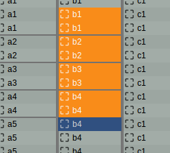
If there is a block selected on the X-sheet, the player window plays only the frames within the selected part of the scene. Since it is relatively easy to select a block on a single frame, if the player window shows only the same single frame and not playing, first try to replace the cursor on the exposure sheet, to deselect the block you created accidentally.
The Level properties window for a level can be opened from the exposure sheet by clicking on the letter mark in the level header, and also can be opened by clicking twice on the list of the projected levels in the player window or in the mover editing window.
There are effect types that you can enter to the exposure sheet, but also you can set for a level statically. The effects written in the X-sheet are superimposed on the values set here. This solution mainly useful in a linetest, when the background needs to be faded quickly, or the shadow level needs a different color. For final works, this solution may not be accurate enough.
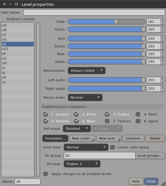
At the top row of this window you can set the own name for the level. This is the same name as the field beside the letter mark on the level header on the exposure sheet. This name is unique to the level and cannot be redirected, it is empty by default and it is possible to set levels to the same name.
At the bottom left corner of the window you can change the identifier of the level content in the Name: field. Over this input field, there is a list with ll of the level contents of the scene. If you click on any of them, you redirect the level content. A redirected content means that the level is sharing its exposure sheet content with another level. The change in one will change in the other too. You should take consideration that the level content which is not used by any of the levels will be deleted from the scene.
Picture and sound effects that can be set in this window:
Fade:
transparency of the level, similar to the //fade effect,
Focus:
the unsharpness of the level, similar to the //focus
effect,
Red:, Green: and Blue:
recoloring, similar to the //red , //green ,
//blue effects,
Alpha:
transparency hardening, similar to the //alpha effect,
Left audio: and Right audio:
the volume of the left and the right audio channels, similar to the
//left and //right effects,
Stereo audio: menu:
in the program, a sound can be mono or two channels stereo. The mapping of the stereo sound channels can be selected from the menu. The possible values:
Normal - the left channel of the sound is the left, the right is the right side,
L-R Swapped - the left and right channels of the sound are swapped,
Mono - the combined left and right channels will sound on both sides,
Left only - only the left channel will sound on both sides,
Right only - only the right channel will sound on both sides.
Enabled picture sublayers:
In this section you can select which of the sublayers (1. Generic, 2. Effect, ...) of the pictures to be projected. This way it is possible to keep the related data in a drawing together (outline, paint, mask etc.) under a single name, but in the levels of the exposure sheet these can be used separately or together. This is also helped by the fact that the level content can be redirected to another, so the same level content can be used multiple times in the exposure sheet. You can switch on and off the individual sublayers with the 1, 2 ... keys. The C key clears all of the switches, and the I key inverts their states.
Self-mask:
This setting simplifies the usage of a common effect type. With this solution at least one extra X-sheet level can be avoided. The contents of the selected picture sublayer (usually a mask painted in the computer) can be combined in the following ways with the normal contents of the picture:
Disabled - the function is switched off (default),
Positive - the selected picture sublayer behaves as a Positive mask, so the contents of the other sublayers are visible only where the masking sublayer is not transparent,
Negative - the selected picture sublayer behave as a Negative mask, so the visibility of the other sublayers will be controlled by the inverse of the transparency of the mask,
Shadow - the selected picture sublayer will be rendered as a self-shadow by Multiply mode, masked to the other sublayers. In this mode you can save two other X-sheet levels (a mask and a shadow).
Templates...
With this button you can save the properties of individual levels or groups of levels to templates, which can be reused in another scenes too. It is possible to make a live connection to a template, when the change in the template changes the properties of the level too.
New under and New over
You can create new levels under and over the edited level with this button. The new level gets the same properties as the current level. The buttons have a menu with these options:
New empty level - it creates a new, independent, empty level by copying the properties of the edited level,
Redirect to this - it redirects the contents of the new level to the current one. The two levels will have a common content,
Set group for this - it creates a new, independent, empty level with a default level group, which will point to the current level.
Unshare
If the level content was redirected, therefore it is shared with other levels, by using this button you can convert the content to individually editable again.
Delete
This button deletes the current level. The level content will be lost after deleting, unless it is shared with another layer.
Level type:
In this menu you can set the mode in which the contents written to the level is interpreted. There are many available level types to process pictures and movers. For example, the same picture can be a viewable drawing or a mask to modify another level.
On group:, Level groups...
If the level modifies the content of another level, such as a mask, mover, or effect, there must be some way to specify which layers to change. The level group is a combination of levels of the exposure sheet, which can be referred to by its name. You can specify the default level group for the level in the On group: field (it is All by default which means all of the levels). This can be overridden in the X-sheet entry for motion paths and effects. The default level group can be used as a pegbar posion if the On pegs: option was set to the Group pegbar value. By clicking on the Level groups... button, you can open the settings window for level groups.
On pegs:
With this option you can assign a pegbar to the level, which can be used to control the position and size of the level contents in the image field.
Apply changes to all enabled levels
If this option is switched on, the modifications in the Level properties window of the current level (except redirecting) automatically applied on all enabled levels. If the option is “half on”, the levels contained by the default level group of the current level will be modified. This will help you to speed up the configuration of the levels. The current level always will change, even if it is not selected by this rule, for example, if switched off in the exposure sheet.
Many times you may need to enter a level into the exposure sheet in multiple copies parallelly. This can be necessary, for example, when you want to use the same picture sequence as picture and mask at the same time.
Redirecting the level content allows you to include a level in the exposure sheet in multiple copies. The redirect affects only the content of the level, that is, the data entered on the frames, not the other properties of the level (level type, level groups, pegs position, transparency etc.). These can still be individually set up for each level.
In the Level properties window of the level, the list on the left shows all the level contents in the scene. A level may contain any of these. After clicking on the letter mark of the desired level content, the program asks for confirmation, then after clicking the Redirect button the level switches to the selected content. If the old level content is not used by any level it will be deleted. The same level content is always the same in all the levels referring to it, and the changes in one level change in all the rest too.
The program can interpret the content of the exposure sheet levels in several ways. You can set the level type in the Level properties window of the level, with the menu of the Level type: button.
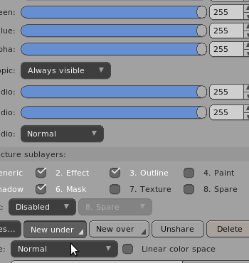
Below you can see the menu name of the level type, and then comma separated, the letter mark as appearing in the level header.
Picture rendering, color mixing:
The content of these levels is involded in creating the colors of the rendered image. These level types can be masked by other, mask type levels.
Normal
- This is the default, the pictures are displayed with their own original colors and the contents of the upper level cover the underlying levels according to the transparency of the picture.
Shadow, _
- The colors of the level are replaced by black, while keeping their transparency. Then effects can be used to make this more transparent, different color or blurred. You can make a drop shadow with replacement and distortion, but this can be useful for other effects too.
Add, A
- This copies the picture with additive color mixing to the contents of the underlying levels. Its effect is like projecting a picture onto a surface.
Subtract, S
- This copies the picture with substractive color mixing to the contents of the underlying levels. It has the effect of mixing paints or printing them over each other.
Multiply, M
- The result comes from the multiplying of colors. The color components determine the blending ratio of the underlying contents to black. This is specially useful for shadow effects.
Screen, Y
- This is an “inverse multiply” operation. First inverts the colors, then multiplies them, then inverts the result again. This increases the luminosity of the picture.
Overlay, O
- This mode makes mid-tone colors brighter or darker by bending the transition between minimum and maximum upwards or downwards, according to the value of the color component. It is similar to the Overlay mode you can find in other drawing programs.
Recolor, C
- It works similar to the Normal mode, but keeps the
transparency of the existing picture content. It can be particularly
useful if you combine this mode with the composed levels effect (
//comp ). You can paint over the contents of other levels
this way, without masking artifacts at antialiased edges.
Difference, D
- The color of the result is the absolute value of the difference between the components of the two mixed colors.
Masking:
These level types mask other levels, some parts of the other level can be changed transparent and removed. In this case the transparency of the content of the other level is controlled by the transparency of the mask level. The color of the mask will not be used. Mask levels do not affect each other, there is no masked mask option. But using the varied mask types, all cases of masking are still feasible. The default level group of the mask level selects the masked levels.
Positive mask, +
- The masked level will be visible where the mask is not transparent. The positive masks modify the masked level one after another individually, so the masked level stays where each of the masks has opaque image content. The result does not depend on the order of the mask levels in the list.
Negative mask, -
- It is similar to the effect of the Positive mask, so it masks individually but the inverse of the mask's transparency effects, so the masked level stays where the mask is transparent. The result does not depend on the the order of the mask levels in the list.
Separation mask, /
- A variation of the Negative mask type, but it removes the content of the mask as a separated part of the masked picture. So if you add the mask content back on another level, the transparency of the merged result will be exactly the same as the original picture. Sometimes you need to separate some parts of a figure into a separated layer to composite something between the original picture and its separated part. The separation mask erases the area of the separated part, so there will be no visible seams caused by the combined opacity at semi-transparent edges.
The following level types are union type masks. These are copied to each other before masking and the merged result will be the mask. The content of the masked level stays where the unified mask is not transparent. The result depends on the order of these levels in the exposure sheet.
Union mask, U
- Union type, positive mask level. The result will be visible if at least one union mask is not transparent at the given location. Otherwise, its effect is similar to Positive mask.
Neg. union mask, N
- Union type, negative mask level. Its effect is the same as the Union mask type, but it uses inverse transparency of the mask.
Eraser union mask, E
- Union type mask, its contents erase from the resulting mask of the pre-masking unification. For this type the result depends omn the order of the masks in the list, because the contents of the later following masks write over the erased parts. The order in witch the masks are merged is the same as the order of the levels in the list.
Neg. eraser mask, W
- Union type mask, it erases from the unified mask the same way as the Eraser union mask type, but it uses the inverse of the transparency. The result depends on the order of the masks in the list.
Exclusion mask, X
- Union type mask, the result is the difference between the mask transparency and contents of the unified mask. Where the mask is transparent the resulting mask remains unchanged, where opaque, the resulting turns to its inverse. The result depends on the order of the masks in the list.
The following level types are special cases of masks:
Unfocus map, F - The transparency of the mask
level modulates the unfocusing of the masked levels. Where the mask
picture is transparent, the masked picture remains sharp. The unfocus
masks affects individually, one after another.
Directional focus, =
- The transparency of the mask and the color components modulate the unfocusing of the masked levels in the own coordinate directions of the picture. The transparency affects all directions (just like with the Unfocus map mode), the red from right to left, the green from top to bottom, and the blue from bottom up adjust the strength of unfocusing. With this level type you can make directional blur and motion blur effects.
Inter-scene mask, #
- It has effect only when in the Playlist window you select the Keymask mode in the Transition: menu between two scenes. The connection between the two scenes will be determinded in the overlapped part by the content of the inter-scene mask layers. Such layers can be written in both connecting scenes and the masks determine how the contents of the second scene will be placed above the contents of the first scene. For simple cases it is more convenient to use the Overlap and Underlap moves, where no masks are needed but the results are calculated with the own transparency of the scenes.
Processing movers
The program can interpret the movers in different ways too, by default the movers are modifying the position, scaling and rotation of the pictures. The location of the motion can be given with two vectors, the position vector and the size vector. The position vector specifies the translation in horizontal and vertical directions, and the size vector determines the scaling and rotation of the picture layer. The following level types can give you different interpretations of these movers. The position, scale and rotation information will remain but their meaning will become different. If you enter pictures into such levels, the pictures will behave as picture vector positions and they will act the same way as movers.
Light rays effect, R
- Starting from the current position of the motion path, like from a point, it radially blurs the affected image. The result will look like radial motion blur or light rays. The strength of the unfocusing will be determined by the length of the size vector, and its direction (inwards or outwards, or both) will be defined by the direction of the size vector, as its horizontal and vertical components.
Picture vectors, V
- The pictures entered into this level used by the program as picture vectors, i.e. motion positions. Each picture can contain at most eight position vectors, and can be enabled or disabled with the switches of Enabled picture sublayers:. This function is useful when correction needed in the positions of the pictures of an animated sequence. In this case you can duplicate the level of animation as a picture vector level, then the pictures can be used as their own self-correcting positions.
Deformation path, T
- This level distorts the modified level by directional scaling and shear. The layer can be scaled in the direction of the size vector, by its length, and the level can be sheared in X and Y directions according to the coordinate components of the position vector. The deformation does not change anything if its base point is (0,0) and the length of its size vector is 1.
Perspective path, P
- The horizontal and vertical components of the position vector distorts the matching side of the picture by shortening it towards the corner to make a rectangular trapezoid shape. Only for simple cases, usually it's more convenient to use a 3D program.
Mirror path, %
- It mirrors the picture using the direction of the size vector as an axis, which goes through the position vector. It also scales the picture by the length of the size vector, out from the location of the position vector.
3D position, Z
- The Y coordinate of the motion path moves the picture in the Z direction (depth direction perpendicular to the image plane). The other parameters of the motion path are ignored.
By enabling the Linear color space option, the colors will be calculated in linear (physically correct) color space. The default color space for compositing is sRGB, but some operations, like the unfocusing, can give better results in linear color space.

For a well arranged exposure sheet it is not recommended to mix the purpose of levels, i.e. do not use the same level for both pictures, sounds, effects etc. Create separate levels for these different purposes. It is also better not to specify the level group together with the effect in the exposure sheet, instead, use only the default level group in the level properties to set the combination of levels.
When you enter some kind of effect, mask or mover into the X-sheet, it is also necessary to determine which levels are affected by. The meaning of the level group is a particular combination of levels. It is like the combination when you see which levels are switched on for playing and which are not. The level group contains a combination and you can refer it by the group's name. It can hold any number of levels from the scene, in any combination. There can be at most 128 level groups, which will get the 01 .. 7F (hexadecimal numbers) names by default. These names are free to change and valid within the scene. You can refer to the same level group multiple times in the scene and it will mean always the same combination of levels.
From the Level properties window the Level
groups... button opens the setting window of the level groups.
Each levels can have a default level group which is used when the
level group is not specified with the effect or mover in the exposure
sheet. In mask picture levels it is not possible to enter a level
group together with the names into the exposure sheet, so the masks
will mask always the levels of the default level group. The default
level group for a level is “All” by default, which
means all of the levels (which are enabled for playing).
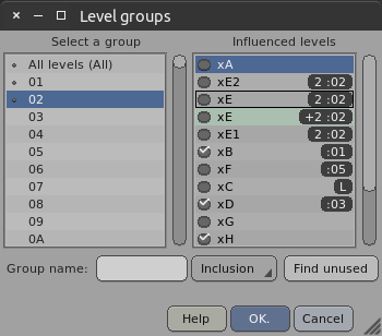
The Select a group list on the left in the window contains all of the level groups. The cursor row in this list shows the selected level group. Non-empty groups have small marks in front of their names on the list. By clicking on one of these groups with the right mouse button, in the menu you can combine its content with the content of the selected group:
Copy group - copies the content of the group into the selected group,
Include group - merges the content of the group with the selected group,
Exclude group - leaves out the content of the group from the selected group,
Common with group - keeps only levels that are common in both groups.
The default names of the level groups are serial numbers between 01 .. 7F (it is hexadecimal to keep compatibility with the old versions of the program, the digits are: 0-9 and A-F), but you can rename them with the Group name: input field.
The list, named Influenced levels on the right shows the levels of the exposure sheet. You can set the selected level combination for the selected group here. You can include the certain levels in the group by using the checkboxes next to the level names.
On the list of levels you can select multiple levels at the same time. The rows of these selected levels have different color. Selecting the levels does not change their group inclusion. There is a right mouse button menu of this list, where you can do the following operations on these selected levels:
Include selected, Exclude selected, Invert inclusion - changes the inclusion of the selected levels in the group,
Cut, Copy, Paste - copies/pastes the group inclusion state of the selected levels between groups. The cut operation also excludes the selected levels from the group,
Select dependencies - selects all levels that has any influence on the levels of this group (levels of applied effects, movers, etc.),
Select all - selects all levels on the list,
Invert selection - inverts the selection.
There is another way to include levels to the group while the level groups window is open, when you click on the letter mark or the checkbox on the level's header in the exposure sheet window with the Right mouse button, Middle mouse button. Also there are menu items for this in the right button menu of the level header - Add to group or Remove from group, these can also be used while the groups window is open.
Find unused - finds and selects an unused level group on the left side list,
Inclusion - with its menu you can include or exclude the selected levels in the selected group, or you can invert the inclusion of these levels.
You can select multiple levels on the list to apply these changes on them at once. There are right button menus on both the list of groups and the list of levels to copy selections between level groups easily.
By clicking on the OK. button the window will be closed and the selected level group becomes the default level group of the level. The Cancel button also closes the window but the default level group in the level properties window remains unchanged.
In cartoon animation they use pegs for the motion steps to precise fit them together. The size is standardized, every paper has three positioning holes, the middle is circular, the sides are narrow rectangular shapes. The papers can be inserted on a pegbar with three pegs matching to these holes, this way the papers are always at the same position relative to the other papers and to the pegs.
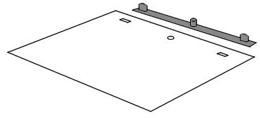
The Firka program also use pegs to position the drawings. The drawings does not normally contain pegs, like when the pictures captured with a video camera, or when an external file loaded. But the pegs position can be recognized on the drawings by the program, using the images of the peg holes. The own peg hole positions for the drawings can be adjusted also manually in the mover editing window.
The pegs are switched off in the levels of the exposure sheet by default. This means the drawings always placed at the center of the image field, so that their height fills the image field in the vertical direction. This base position can be changed with movers. To enable the positioning by the pegs positions of the drawings, the contents of the level must be placed on a pegbar, i.e. you have to set a peg for the level.
With the pegbar, position, scaling and rotation of the drawings are all adjustable. From this point of view, a pegbar is similar to a still position mover in the exposure sheet. With a pegbar you can replace drawings which don't have peg hole positions too. These drawings receive a default peg holes position.
In the Level properties window of the X-sheet level, use the On pegs: menu to place the level contents onto one of these pegs positions:
None
This is the default, no pegs, the drawing always fills the image field vertically,
Level's own
The own pegbar of the level, it is an individual position which is independent of the other levels,
Group pegbar
A shared pegs position, controlled by the level group in the On group: field. For each of the level groups, a separate pegbar position can be stored and levels referencing the same group pegbar get the same position. Because this mode interferes with the free usage of level groups, it should be used only if all of the Pegbar 1 ... Pegbar 13 pegbars are already in use.
Pegbar 1, Pegbar 2 ... Pegbar 13
Shared pegs positions, the most commonly used pegbars. These are the easiest settings if the contents of two or more levels are sharing the same common pegbar.
The shared pegs are valid inside the scene, sharing pegs between scenes can be done with templates or with unifying scenes, when the scenes are just different exposure sheet views of the same database scene. This rarely needed, it is most convenient to save the pegs position from one scene and load it into the another. You can save and reload the pegs position for an xsheet level easily in the mover editor window after switching the Exposure sheet mode option on.
If a level is set to a pegbar position that has not been used yet in the scene, the new pegbar inherits the previous pegbar position of the level. With this feaure you can place the level to a different begbar. You can change the position from, for example Pegbar 1 to Pegbar 2, and the new pegs position will remain at the same place, from where it can be replaced.
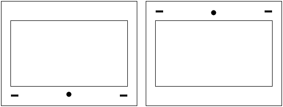
When the pegbar changed from the None position, the pegbar gets a default postion. This default position can be below or above the image field, depending on what was set in the About window. When working with animated drawings on paper, this should be set to the same method what animators actually use. Otherwise the bottom pegbar is more useful, because when you place a drawing without own pegbar data on a bottom pegbar, it will remain on its original position, similar to the None mode. While with top pegbars, such pictures will be upside down, because in the absence of pegs information the program always assumes bottom pegs, so it places the assumed pegholes under the lower edge of the picture. The None mode does not use the pegs position information from the pictures, but the other modes do. In these other modes, pictures that actually have their own pegs positions will be placed according to these own pegs positions. So to match the top pegbar position correctly, the program attaches pegbar information to all newly created picture items in the top pegbar mode.
Sometimes the properties of one X-sheet level should be used in one or more other scenes, for example two consecutive scenes should use the same pegbar position or the transparency of two layers should be exactly the same. In these cases you can use a template, which creates a connection between levels of different scenes.
You can open the window of templates from the Level properties window of the exposure sheet level, by pressing the Templates... button.
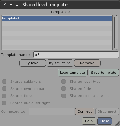
A template can be made in two ways. You can create a template from the standalone level with the By level button. Or, by pressing the By structure button, it will also include the duplicates of the level and all the other levels whose default level group refers to the level or to its duplicates.
After the template is ready, it can be used in any of the scenes of the movie. To achieve this, open the window with the Templates... button in the properties window of the other level, then select the template and click on the Connect button. If the template was made with the By structure button the program creates the additional levels as new levels and connects them to the template too.
When you create a template, the copied levels will automatically connect to the template. You can detach the level from the template by clicking the Disconnect button.
You can set which properties you want to attach to the template by using the Shared sublayers, Shared level type ...etc. switches. If you change a property that is connected to a template, the program asks you how to keep the level and the template in sync: update the value in the template to pass the new value to the other connected levels, or disable the connection of the property, or restore the original value from the template.
The template is valid only within the movie in the database. The levels are using the name of the template to connect. If the referred template is missing from the movie, the level behaves as if it were not connected to a template. If you create the missing template again, the level will re-connect to it.
The program draws the levels into the picture by the order in the exposure sheet, one after another. The opaque contents of higher levels obscures the contents of underlying levels. When masking a level, the masks are also applied by their order in the X-sheet.
Sometimes, it can be important to know the order of the calculation of effects and settings on a level. This order is fixed, and if a different order needed, it can be solved with additional steps, like with the //comp (Compose levels together) effect.
Rendering of a picture is done in the following order:
1. Merging the sublayers of the picture
2. Self-masking (according to the level property)
3. If the level type is Shadow, recoloring the picture to black
4. Unfocusing ( //focus )
5. Inverting ( //invert )
6. Saturation ( //saturation )
7. Recoloring ( //bright , //dark , //red
, //darkred ...)
8. Amplifying color ( //amplify )
9. Transparency from color ( //from )
10. Amplifying Alpha ( //ampalpha )
11. Alpha contrast ( //alpha )
12. Alpha threshold cut ( //threshold , //thres_pad
)
13. Hard Alpha ( //hard )
14. Fade transparency ( //fade )
15. Perspective distortion
16. Applying morphs
17. Ray effect
18. Applying masks
19. Applying unfocus maps
Unfocus maps are applied after the masking, so if something need to be blurred after the masking (so the masked edges are also blurry), it can be done with an unfocus map level. Contrary, as the focus effect comes before masking, the mask remains sharp in that case.
You can open the record window from the window of the exposure sheet, by clicking on the Record button. The tabs at the top right corner of the window select the editing mode:
Pictures
- in this mode you can create and edit picture item types. In this mode, right below the tabs, there are two additional buttons to select between two modes:
Record - to camera record and scan pictures,
Paint - to edit, draw and paint pictures.
Sounds
- select this tab to edit sounds and cut them, and also this is the place to breaking down dialogs.
Movers
- at this tab you can edit movers, and also here you can position levels and pegbars in the picture field.
Use the Close button to close the window, and with the Help button you can ask for a written help about the usage of the window.
There is also a Save scene button at the top right corner, to save the scene during works without the need to close the window. This button has the same function as the similar button on the exposure sheet window, and you can also use the Save as button functionality through its menu.
On the right side, like in the X-sheet window, there is the list of items. Under the list there is a narrow button to hide the control elements below the list, in case if you need more space for the list.
When the Thumbnails is switched on, the list shows thumbnail pictures next to the names. The three sizing buttons next to the switch control the size of these thumbnails on the list.
The Path: field shows the access path of the listed item folder here too.
The Item: field contains the name of the item which is under editing. When you create a new item in any of the modes, enter its name into this field.
For capturing pictures, the Pictures tab shoud be active at the top right corner of the window, and also the Record button should be selected under it.
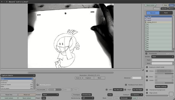
At the bottom left corner of the window, above the settings list, you can see a long button. This button is actually a menu, with which you can select the active capture device. If you have such hardware in your computer (scanner, video camera, webcam etc.), they appear on the list and you can activate any of them, even during capture. If the selected device has a settings window from its manufacturer, it will appear after you selected the device. In this window usually you can set the resolution, the input channel, the color system etc.
If you connected a device on the go, it may not appear on the device list. It is recommended to switch the button to Not selected (or No input device), even if it is already selected. Then the new device will most likely appear on the list.
By moving the slider's position below the picture to the right, you can show the raw picture from the camera on the side to the left of the slider position. This can be useful, for example when the picture has poor colors and you want to know that the problem is the picture from the camera, or the settings.
You can zoom in the viewing to check the quality of the pixels, for example if the display resolution is lower than the resolution of the incoming picture. You can use the Numpad-1 ... Numpad-9 numbers on the numeric keyboard, to set the zoom value. If the mouse pointer is over the picture, it zooms to the pointer's position, otherwise it zooms to the center. With the Plus (+) and Minus (-) keys you can zoom in and out step by step. The mouse wheel is also usable for zooming when the mouse pointer is over the picture field.
Additionally, you can use the zoom slider and the positioning tool at the bottom right corner of the window, or the scrollbars around the picture. With the arrow keys on the keyboard, you can move the visible area. If you click on the picture with the Ctrl+Left mouse button, Right mouse button, Ctrl+Middle mouse button and drag the mouse with pressed button, you can increase (by dragging down) or decrease the zooming (by dragging up). If you drag the mouse on the picture with the Shift+Left mouse button, Middle mouse button, Shift+Middle mouse button, you can change the location of the visible area.
The controls at the bottom right part of the window are the same in both the Record and Paint modes.
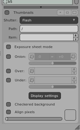
The Item: field contains the a1 name by default,
the program offers it as a usual first picture name for capture. This
can be modified manually if something other needed.
You can use the Shutter: menu to specify what visible or audible effect will indicate the exposure.
Below these fields, the Onion: switch enables the onion skin mode, in which the previous and next pictures from the list are visible together with the displayed picture. It is specially useful for stop motion animation. In this mode the previous pictures get a blue tint, and the next ones get a red tint by default. You can change these colors with the Display settings window, see below.
At the side of Onion: switch, the number of viewed previous and next pictures can be selectable with the menu buttons (from 0 to 3). At the middle, use the = button to show the just captured image.
You can click with the Ctrl+Left mouse button, Middle mouse button on the Onion: checkbox to switch on an alternative mode, which works without color tinting. In this case the checkbox will get a different shape, it will be “half on”.
The onion skin mode can be switched on and off also by the Tab, Shift+F4 keys of the keyboard. With the slider below these buttons, you can change the visibility of the onion layers.
When the Exposure sheet mode switch activated, the level of the cursor of the exposure sheet becomes visible at the left edge of the window. It can be edited in a similar way to the X-sheet window, and after the capture the program also enters the photographed picture into the X-sheet level from the cursor. In this mode the onion skin shows you the contents of the X-sheet level around the cursor.
If you do'nt want to write the captured picture into the X-sheet, for example because you re-capture a mistaken picture, you can temporarily switch off the Exposure sheet mode, but you can do it also by clicking on the Capture or Next buttons with the Ctrl+Left mouse button, Middle mouse button. A capture without entering to the exposure sheet can be achieved also with the keyboard, by pressing the Ctrl+Space key.
With the Over: and Under: switches you can put existing pictures over and under the displayed picture, for example to restore a previously used camera position. If you switch either of these functions on, and its name field is empty, the name from the Item: field (the current picture) will be copied into the name field of the activated Over: or Under: function.
The name input fields of Over: and Under: both have the same extended right button menu. This menu has a history with the previously entered names and also contains the following menu items:
Copy current name here - copies the content of the Item: field,
Encode to a rule - converts the entered name into a
differential rule, relative to the content of the Item: field.
A differential rule starts with double slash ( // ) and
will follow the changes in the content of the Item: field.
Follow the X-sheet cursor - enters a rule to follow the xsheet
cursor in the layer it is currently located. It will follow the same
xsheet layer (referenced by its name), even if the cursor moves to
another layer afterwards. The pattern starts with four slashes (
//// ) and can contain either the name of the level or
the name of its content. It references the layer by its name, so there
can be a problem if the name is not unique.
Remove rule - if there is a differential rule or xsheet following rule in the input field, replaces it with the calculated direct image name.
Add to mask - adds the content of the overlay picture to the mask of the digitized picture. This menu item appears only in the Record mode. The mask in this mode is on-off style, there are no intermediate steps in its transparency, so the mask will hide only where the pixels are fully transparent on the overlay picture.
Set as fill pattern - copies the overlay picture into the flood fill pattern in the painting mode. This menu item appears only in the Paint mode, instead of the Add to mask menu item. The pattern will contain the merged visible layers of the overlay, without palette pixels.
With the Checkered background switch you can put a checkerboard texture under the picture to check which parts of the picture are transparent.
By pressing the Display settings button, you can open a settings window to configure some display settings.
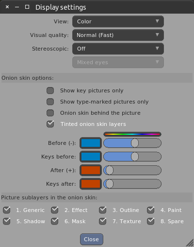
In this window, with the View: menu you can set what color channels of the picture you want to see:
Color - color mode,
Gray - grayscale mode,
Red, Green, Blue - viewing color channels,
Lin. color, Lin. gray - a variation of the color and grayscale modes, when the background is merged behind the picture in linear color space.
With the Visual quality: option you can set better quality rendering modes for the display. It is specially useful when the picture resolution is higher than the display area on the screen.
You can select some stereoscopic view modes with the Stereoscopic: menu button at the right side of the window:
Off - default, no stereo 3D,
“Over” as Left eye, “Under” as Right eye - in these modes the content of the Over: or Under: fields gives the other view for the stereo picture pair.
Left and Right captures - when capturing a stereo photo, and the left and right eye views are both captured, the currently captured one from For the Left or For the Right, together with the already taken image of the other eye give the stereo image.
With the second additional menu button for the stereo menu you can select the 3D view mode (anaglyph, interlaced etc.). These modes are similar to the modes you can set for the player window, and the program even copies the selected mode from there as a default.
There are also options here for the onion skin mode. When you enable Show key pictures only, only pictures that are marked as keys will be viewed. Also, with Show type-marked pictures only, you can restrict the onion skin to view type marked pictures only (as LAYOUT etc.).
If you switch Onion skin behind the picture mode on, the onion layers will be visible only behind the transparent parts of the picture. Otherwise these will be mixed with the picture. Enabling this option may be useful for freehand drawing.
With the Tinted onion skin layers option you can enable or disable the color tinting on the onion skin layers. This option is connected to and shares its state with the “half on” mode of the Onion: switch on the main window. Changing one of them will also change the another.
You can use the buttons and sliders below of these to set the color tint of the onion layers before and after the current one. You can set the color for pictures with and without key marks separately.
There are also checkboxes to enable and disable the eight internal sublayers of the pictures displayed as onions skins.
You can close the settings window with the Close button at the bottom.
These are the steps of a simple pencil test recording:
Place the field chart paper from the scene underneath the camera. Set the sharpness and picture cutout (zoom) on the camera lens. Then set the picture cutout and the resolution in the computer. You may take a photo of a blank paper by clicking on the Get button at the Paper: label. Put the first drawing paper under the camera. Adjust the quality of the picture. It is the best if every lines are clearly visible and the background is full white. The The paper is white setting on the parameter list should be on.
Write the name of the drawing into the Item: input field and click on the Capture button. If the numbering in the drawings is evenly increasing, you should only change the drawing under the camera and click the Next button or press the Space, Ctrl+Return/Enter, Insert on the keyboard. If you mistakenly captured something, you can repeat the last capture with the Capture button or by pressing the Return/Enter key.
It is advisable to save the scene with the Save button from time to time, to avoid losing the captured data because of an error or a power line blackout.
When finished, close the window with the Close button, then you can continue the scene by filling in the exposure sheet.
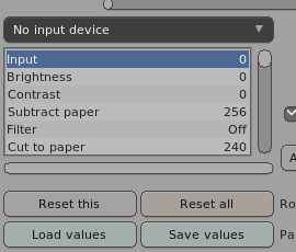
With the settings list, you can control several properties of the picture. After selecting an item on the list, the value of the selected property can be adjusted with a slider or menu under the list.
The Reset this button resets the selected parameter into its default value, and the Reset all button restores the default values for all of the parameters.
The Load values loads all parameters back from a file, and you can save the current settings into a file with the Save values button. The values of the parameters are displayed next to their names on the list.
Certain adjustable properties are:
Input
- if a device has more than one video input channel, and it is not able to choose automatically a valid one from them, this can be used for choosing the input. Under Windows, for Video for Windows (VfW) devices, if the camera resolution is higher than 640x480, you can set the resolution here. Also you should set the input video format for Blackmagic Design cards here.
Brightness
- brightness of the picture.
Contrast
- contrast of the picture, the steepness of the light-dark transition.
Subtract paper
- the subtracting strength of the empty background recorded by the Get button at Paper:.
Filter
- contrast increasing filter, it also increases the sharpness of the picture.
Cut to paper
- the shades between the value and the background (white or black) will be replaced with the background color,
Quantize
- the number of the color grades between black and white. The less the color steps in the picture, the less memory will be used, but the picture will be blobby (posterized). At its lowest setting, there are only two colors used, black and white.
Gamma
- gamma correction. The transition curce between light and dark, it determines that the dark or the light shades will be higlighted against the others.
Noise filter
- a kind of filter, removes small groups of contiguous non-transparent pixels from the image. You can set the maximum number of connecting pixels.
Saturation
- saturation in color mode (divergence from gray).
Red
- red color component proportion.
Green
- green color component proportion.
Blue
- blue color component proportion.
Zoom
- the size of picture cutout within the raw camera picture. For setting zoom, it is better to use the lens on the camera, because this mode is only clipping out from the edges of the picture, therefore the resolution becomes lower. But it is good for removing the picture artifacts at the edges of the camera picture, like noises or stripes.
Horizontal
- horizontal offset of the picture cut by Zoom, within the raw image seen by the camera.
Vertical
- vertical offset of the picture cut by Zoom, within the raw image seen by the camera.
Stretch
- distracting or compressing the picture, aspect ratio distortion.
Transparency
- transparency of the picture. It regulates the semi-transparent levels of the medium bright pixels. It's best to test its effect by switching the checkered background on.
Resolution
- downsampling of the picture's pixel resolution, relative to the maximum possible.
Field width
- the width of the picture in pixels. If it is set to 0 (Off), the width will be automatical based on the resolution of the incoming picture, or you can override this calculation with a certain value. With the buttons at the ends of the slider, or with the right button menu, you can select common standard values.
Field height
- the height of the picture in pixels. If it is set to 0 (Off), the height will be automatical based on the resolution of the incoming picture, or you can override this calculation with a certain value. With the buttons at the ends of the slider, or with the right button menu, you can select common standard values.
Field aspect ratio
- the geometrical aspect ratio of the captured picture field. With the buttons at the ends of the slider, or with the right button menu, you can select common standard values. Its operation is similar to the setting in the movies window. At start, the program sets the same aspect ratio as in the movie.
If the Field width or Field height width settings are not set to Off, you can set the width and the height of the picture in pixels. If both of them are Off, the resolution is calculated from the original picture according to the Resolution setting. If only one of them is Off, then the program calculates the resolution from the frame aspect ratio and the size in the other direction.
The remaining options on the list are switches. You can also switch these on and off by clicking on the checkboxes next to the names on the list.
The paper is white
- it controls whether white or black is the transparent background. Because when capturing the paper drawings, the background is the white of the paper, in this case this switch should be on.
Color mode
- color or grayscale mode.
Mirror horizontally
- horizontal mirroring of the picture.
Mirror vertically
- vertical mirroring of the picture. To turn the picture upside down, that is, to rotate it by 180 degrees, switch both mirror options on.
Negative
- inverse picture, just like a negative film.
Averaging filter
- picture enhancement filter, it merges the last four incoming frames together to decrease noise. This filter needs time to build a clean picture after a change, the result will have ghosts if the picture is not motionless for enough time.
Guide lines
- puts a guide grid over the picture, it may help positioning the camera.
Shadow mask
- shows the transparency with different fake colors. Only the fully transparent parts will get the background color, the fully opaque parts will have a visibly stronger shade than the shadesd of the partially transparent regions. You can switch this mode on or off with the F12 from the keyboard. It only affects displaying, it does not change the captured pictures.
The exposure can be made in the middle of the window, with the Capture and Next buttons.
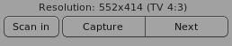
The Capture button stores the digitized picture under the given name, and the Next button makes the same thing, but before the capture it adds the number from the Advance: field to the number in the picture name. For example:
If there is “K0001z” in the Item: field, and
the value of Advance: is 2 , then:
Capture button creates an item with “K0001z”
name, and
Next button creates “K0001z” + 2 , that is
“K0003z” .
This is good to do so because during recording, when a sequence of drawings are captured with the Next button, if the last capture was a mistake, for example the hand of the operator remained under the camera, it is possible to retake the last picture with the Capture button (even multiple times).
You can make a capture by entering a name directly into the Item: field and press the Return/Enter button on the keyboard. This is specially useful if the numbering of the captured drawings is uneven and you have to enter the names manually. By double clicking on a name in the list of items, you can re-capture the existing drawing. You also can make this if you click on the list, and move in the list with the Up and Down arrow keys, and capture with the Return/Enter key.
You can also step on the list with the PgDn and PgUp keys. This works even if the item list is not selected.
If the Exposure sheet mode switch is enabled, the program enters the name of the captured picture directly into the exposure sheet. In this mode the level of the cursor of the exposure sheet becomes visible at the left edge of the window. It can be edited in a similar way to the X-sheet window, and after the capture the program also enters the photographed picture into the X-sheet level from the cursor. In this mode the onion skin shows you the contents of the X-sheet level around the cursor.
The PgDn and PgUp keys are moving the exposure sheet cursor by picture changes in this mode, and it is possible to move frame-by-frame on the X-sheet with the Right and Left keys. In this mode the Next operation can rename the numbering of other pictures after the name, to avoid overwriting existing pictures.
By switching off the Running picture switch, you can stop the continuos live capturing. In this case you can take a new picture with the Scan in button. For scanners there is no such live preview, you can start the scanning with this Scan in button.
Under Linux, when you use gphoto2 to capture images (photo cameras are working this way), pressing the Scan in button makes the photo camera to take a picture in full quality, while otherwise you can see only the lower resolution live preview.
In the Sublayer: menu you can select one from the eight picture sublayer to set for the captured image. This can be important if the picture will be painted or will be drawn further.
With the Feedback from items switch you can re-capture existing pictures. If you click on a picture on the list, it will appear on the display as if coming from the camera. You can set the brightness, transparency, aspect ratio, pegs position etc. just like with camera image. You can reshoot the original picture or you can make a new one. In this mode you can select a sequence of pictures on the list by dragging the mouse with pressed button, or by selecting all of the pictures between the cursor and a chosen item by using the Ctrl+Left mouse button or Shift+Left mouse button combination. Then you can re-shoot all these selected pictures in one pass by pressing the Capture or Next buttons. If you enter an alternate name for the first picture in the Item: field before the operation, a new set of picture names will be created during the capture. Without this, the original pictures will be overwritten with the re-captured versions.
If there are parts on the picture what you do not want, for example eraser marks, notes or the pegholes, you can hide them by masking. You can draw filled shapes over the picture to clear these unwanted parts to transparent. Draw the required shape on the picture while holding down the left mouse button. You can select the shape type with the menu button at the Mask: part:
Rectangle - drawing a rectangle given with its diagonal,
Ellipse - drawing an ellipse given with its diagonal,
Freehand - drawing freehand outline of a filled shape.
You can delete these patches by pressing the Clear button at the Mask: label. To turn the masking into its inverse, click Invert button there. With Load and Save, you can use files to keep your masks and load them back later. The mask automatically deleted if the picture resolution becomes different from the mask.
The Get button next to the Paper: label serves as a background cleaner for the picture. Place a blank sheet of paper under the camera before recording, and click Get. This time the program take a photo of the blank background, which will be subtracted from every digitized picture afterwards. By this procedure the uneven illumination and the lens errors can be vanished from the picture - which can not be filtered off in other way. For switching off the function use the Clear button, also at the Paper: label. From the keyboard, use P to capture the paper, and Ctrl+P to clear it.
On the settings list at the left bottom corner, there is a Subtract paper parameter to control the strength of the paper removing.
At the bottom of the window there is a Deinterlacing: menu to filter out the striping caused by interlaced pictures:
Off - no interlace filter,
Odd field, Even field - keeps only the odd or even half frames from the picture,
Both fields - creates a mixed picture from the odd and even rows.
In traditional animation they are drawing on paper sheets, which has three pegholes in a line near the edge of the paper. Inserting these holes on pegs, small sticks, ensures that the sheets are always in the same position relative to each other and to the image field.
Firka is able to recognize the pegholes on a picture and to position the captured picture according to these. Especially for document feeder scanners, where the position of pages loaded by the scanner are random.
With the Rotate: menu button, you can select from several picture rotating modes:
None
- the picture is visible by its original orientation,
90 degrees right
- the picture is rotated 90 degrees clockwise,
180 degrees
- the picture is upside down,
90 degrees left
- the picture is rotated 90 degrees counter-clockwise,
Configure pegs
- in this mode, the position of the field and the pegbar can be set on the input picture.
The program can recognize the position of the pegs from the peg holes on the paper. You have to set what is the size of the pegs and what is their position relative to the captured picture field. You will need a field guide paper with pegholes. Put a black paper behind the pegholes during the capture to make them visible. Then in Configure pegs mode, place the field and the pegbar precisely to the correct position on the picture. To achieve this, click on the small squares, and move the mouse with the pressed button.
By clicking on the small squares of the field, the Shift+Left mouse button, Middle mouse button turns the field to horizontal or vertical position, whichever is closer to it. Using the same on the pegbar aligns the pegbar to be parallel to the field.
The Ctrl+Left mouse button, Right mouse button moves the pegbar and the field together. Clicking with the Ctrl+Left mouse button, Right mouse button on the side pegs switches the pegbar between three holes mode (animation standard) or two holes mode (office paper punch).
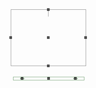
Test recognition
- you can check the recognition of the pegs with this mode. If the program finds the pegholes in the picture, it will put the pegs and the field to the recognized position, and the field will be crossed with diagonal lines, otherwise it leaves them on the position defined in the Configure pegs, without the crossed lines.
Recognize pegs
- recognize the pegs defined in the Configure pegs mode and shows the contents of the accordingly placed image field. When capturing only this visible part of the picture will be saved. The relative position of the pegbar is also stored with the picture, and later, when the X-sheet level of the picture will have a pegbar, the program will align this position onto that pegbar.
By pegs
- shows the picture according to the original position defined in the Configure pegs mode, without peghole recognition. The position of the pegbar will be stored with the picture in this mode, too.
Original on pegs
- keeps the original geometry of the picture, but saves the relative pegbar position defined in the Configure pegs mode together with the picture.
Original
- keeps the original geometry of the picture, without pegs. In Feedback from items mode, if the original picture contained a pegbar position, it will be kept in unchanged form.
Positioning overlays
There are small positioning buttons next to the Over:, Under: and Onion: controls. With these you can replace the overlays. By default the program places the overlay pictures so that their pegs are aligned to the pegs position of the current picture. But you can use these buttons to change it.
For example, this can be useful when creating pictures in-between them. Click on the button to make it active, then drag the overlay picture on the display with the mouse. Click on the button again to switch off this positioning mode. Or you can also move the picture if you click on the positioning button with the Shift+Left mouse button, Middle mouse button, Shift+Middle mouse button and drag the mouse with pressed button. By clicking on the button with the Ctrl+Left mouse button, Right mouse button, you can reset the position of the overlay to its original.
With the X key you can place a small + mark on the picture at the mouse pointer. If it is there, the overlay picture will rotate around the + mark. You can remove this mark if you press X while the mouse pointer is outside of the picture area. You can also use the Ctrl+Delete for this, regardless of the mouse position.
Use the H key instead, if you want to rotate and scale the overlay.
Multiple exposure
You can make multiple exposured pictures with the Accumulate button. It stores the picture into a copy, which will be merged with the incoming picure. If you exposure over the same frame multiple times, more and more captures will be merged together. This is a common way to make motion blur in stop motion animation. You can change the picture mixing ratio with the slider and the numeric input field next to it. The Clear button removes the accumulation from the picture. The accumulation also will be erased after a picture capture. You can use the A, Divide (/) keys for Accumulate, and the Ctrl+A, Multiply (*) key combinations for the Clear operation.
Chroma keying
By default, the white or the black color used as transparent background, as selected by the The paper is white switch on the settings list. But it is also possible to make parts of the picture transparent by their color, as in the bluebox, greenscreen techniques used. For this mode click on the Chroma key button at the bottom part of the window. Then a new settings window appears.
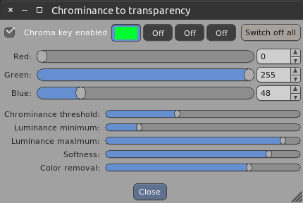
The mode can be activated with the Chroma key enabled switch. At most four color hues can be set for removing, as represented with four color buttons next to the Chroma key enabled switch. You can switch them on and off by clicking on them. When you click on the camera image while the chroma key window open, the clicked color will be copied into the selected color button. With the Switch off all button you can clear all settings at once.
Use the Red:, Green:, Blue: sliders to set the desired color manually.
With the sliders under this, the color removal parameters can be adjusted.
Chrominance threshold: - specifies how much the color can differ from the set value to remain transparent,
Luminance minimum: and Luminance maximum: - the brightness range, within which the color is transparent,
Softness: - it regulates how smooth the transition is for the partially transparent colors,
Color removal: - strength of the key color elimination, this is important for the partially transparent colors, to remove the key color tint from the picture.
If the chroma keying is active, the Chroma key button indicates this with a different look. The chroma keying mode remains active after the close of its settings window.
Timelapse recording
It is possible to make timed recording, for this click on the Timelapse button on the record window. Then a settings window appears.
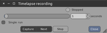
The upper line of the window shows the current state, this counts back the seconds during capture. Under it, you can set the time distance between captures with the seconds slider and numeric field.
If the Single run is on, only one picture will be captured, otherwise the capture will be continuous, the counter will restart after each shot.
You can start the timed capture with the Capture or Next buttons in this window.
By using the Stop button you can stop the timed recording.
Cropping the edges of the picture
Mostly with pegs recognition, when the position of the picture will be determined by the pegs and not by the fixed image field, it is worthy to leave out the empty transparent parts around the real picture content. With this the rendering will be faster and the scene will take less space.
The crop window can be opened by clicking on the Crop button.
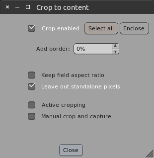
The mode can be activated with the Crop enabled switch. Then a frame appears on the screen, which you can reposition with the small rectangles at its corners. After cropping, only the part within the frame will be preserved in the picture.
The frame can be stretched to the entire picture with the Select all button.
The Enclose button aligns the frame around the current content of the picture, by leaving out the transparent edges around the content. In Feedback from items mode, if multiple pictures are selected on the list of the record window, this operation parses the selected pictures and includes all their contents within the frame.
The Add border: setting controls how much empty space to leave around the real contents of the picture when cropping automatically.
With the Keep field aspect ratio switch, the cropped picture part keeps the original aspect ratio of the picture. With the Leave out standalone pixels mode on, single pixel noises will be avoided during automatical cropping.
When the Active cropping is enabled, an auto-recognition is performed when capturing, and starting from the given frame, the program shrinks the picture to its real content so that it leaves the Add border: frame around the recognized content.
If the Manual crop and capture is on, the cut frame can be drawn onto the picture with the pressed left mouse button. When the mouse button is released, the program captures the cropped picture, like when using the Capture button.
Only one of Active cropping and Manual crop and capture may be active. If both are switched off, the program will crop the picture to the given frame.
Stereoscopic photos
When capturing, you can use the For the Left and For the Right buttons to set the two eye views of the stereoscopic picture. While one of them is active, the recorded picture will belong to the selected eye. When switching, the last picture is preserved. After the Capture clicked, depending on the state of the Left: and Right: switches, these pictures will be saved into the captured picture as sublayers.
You can also draw and paint in the Firka program. In a line-test, you can erase some parts of the picture, or you can paint the inside of the figures with white, to cover the background behind them. Or you can use these functions even to create animation or color painting.
To open the picture editor in the program, click on the Record button on the exposure sheet window. Select the Pictures tab in the window that opens, then activate the Paint button under it from the Record and Paint buttons.
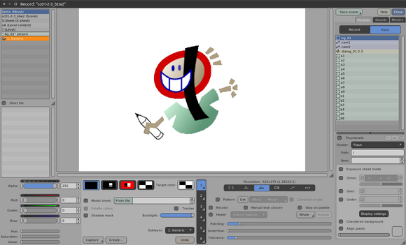
The right hand side of the window is similar to what is available in the digitizer mode and you can read more about these controls in Chapter 7.1. You can find the drawing tools and controls on the bottom part of the window. There are also two lists at the left side of the window: the hierarchy list and the list of the selected palette.
In Firka, a picture can contain up to eight overlapping sublayers internally. A sublayer is a pixel image, which can contain both RGBA and indexed palette colors. The RGBA pixels contain directly their own Red, Green, Blue and Alpha (transparency) components, while the palette color pixels can reference up to 256 palettes with up to 256 RGBA colors per each, and also they have per-pixel Alpha transparency. Additionally there is a fully transparent color, which is a separate third color type, without components.
The bottom part of the window can be divided to three zones. The first part at the bottom left corner is usually a color mixer with the Alpha, Red, Green and Blue components, but if you select something on the two lists at the left side of the window, the available operations for the selected item will appear also here.
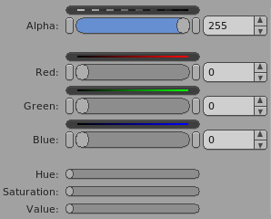
The parameters:
Alpha: - the transparency of the color, between 0-255, 0 means full transparent. Some drawing tools use this transparency as a parameter, for example this controls the strength of shrinking or expanding of outlines.
Red:, Green:, Blue: - the RGB color value. Firka uses 8 bits color channels in sRGB color space, the value range for the components is 0-255. With the small buttons at the end of the sliders you can set the 0, 128, 255 values, and the values of the other components too, by step over.
Hue: - the hue of the color on a rainbow range.
Saturation: - the saturation of the color, the proportion of the weakest component relative to the value of the strongest component.
Value: - the brightness of the color, it is matching to the strongest color component.
Above the sliders, in case of there is enough room, there are colored stripes, which shows what colors can be produced by changing the given slider. By clicking on these and removing the mouse with button down, a menu-like surface appears, where you can select additional color variations.
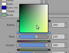
On this surface the horizontal direction corresponds to the parameter values of the slider, the bottom edge of the square is similar to the original color stripe of the button.
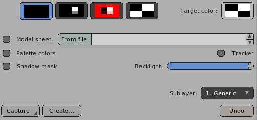
In the second area, which remains the same during the operations, there are four color buttons, and one another labeled as Target color:. The four buttons contain four colors, from which you can select the color for drawing and painting. One of them is always selected. You can switch between these colors if you click on the buttons. At the center part of the button you can see the color's transparency over black and white background. If the button shows the tansparent color (Alpha value is 0) you can see a black and white checkered pattern. To distinguish them, the size of the displayed rectangle for palette colors is smaller than for RGBA colors.
You can switch a button between a specific color and the button's previous color if you click on the button with one of these:
Ctrl+Left mouse button - for transparent color,
Shift+Left mouse button - for opaque black RGBA color.
You can change the transparency of the selected color to full opaque with the Y key.
The following operations are available in the right button menu of the color buttons:
Set to transparent - set the color button to transparent,
Set to black - set the color button to opaque black RGBA color,
Set selection basis and Clear selection basis - in selection by color modes the color of the selection will be the color of the given button, regardless of which color button is active for drawing at the moment. When this mode is on, you can see a dashed frame around the color on the button.
Copy this color - remember the current color of the button for copying,
Paste from copy - paste the remembered color to the color button.
Copying and pasting the color of the color button is working between scenes too.
To pick a color from the picture and copy it into the active color button, move the mouse over the color and press the G key on the keyboard.
The Target color: button serves as a second color parameter in some operations, and by default it contains the transparent color. If you click on the Target color: button, you copy the selected color button into it. The target color can be picked from the picture with the T key.
A color model picture can be viewed at the bottom left corner of the window, you can pick colors from it. To view it, enable the Model sheet: option and enter a picture item name into the input field. You can load an image file with the From file button. You can zoom in and move inside the color model too, the same way as you do with the main picture view.
If you select a palette color from the lower list at left, the Palette colors switch automatically becomes on and you can see the controls for the palette colors. In this state you can draw with the palette color. To return back to RGBA colors switch Palette colors off.
The Shadow mask option shows the picture in distinctive signal colors. Parts that are exactly similar to the selected color will become red. Other RGBA pixels are viewed in blue and other palette color pixels in green. The pixels from the selected palette are viewed in a different green than pixels from other palettes. Also, if the Target color: button's color is not transparent, you can see the target color pixels in light gray. The fully opaque pixels in this mode are significantly darker than any semi-transparent ones.
By clicking on the switch with the Right mouse button, Middle mouse button, you can view the picture in shifted false colors. This way you can distinguish similar palette colors from each other. If this mode is on, you can see these false colors on the list of the palette and on the color buttons as well.
You can toggle this option on and off by using the Space, F12 key, use it together with the Shift key for the half switched mode.
When switching to the next picture, sometimes the same viewing position is not ideal, usually because the character is moving fast on a larger canvas and you are using zoom to paint details. So you need to scroll the display to the right position manually. If you switch Tracker on, the program will remember the last drawing position for each pictures, and will center the view around it after you switch to a picture. This way while you're drawing or painting a moving character, the displayed position will follow the location better.
You can change the brightness of the background behind the picture with the Backlight: slider in the row of the Shadow mask switch. Additionally, with the Checkered background switch at the right side of the window, you can put a checkered pattern background behind the picture.
There can be up to eight sublayers inside a picture. Select the sublayer for drawing with the Sublayer: menu. If a sublayer already exists, you can also select it on the hierarchy list at the left top corner of the window. On this hierarchy list you can see an asterisk (*) in front of the name if the sublayer is selected for drawing but it is not existing yet. On the hierarchy list you can enable and disable the sublayers by clicking on their checkmarks. A disabled sublayer is not visible and not participates in the drawing operations.
By clicking on the switch with the Right mouse button, Middle mouse button, you can switch the layer off partially, which will be represented by a “half on” state switch. A partially disabled sublayer still viewed with half transparency, but otherwise it behaves like a disabled sublayer.
When you select a sublayer on the hierarchy list, other new controls will appear at the bottom left corner:
The slider controls the transparency of the selected sublayer. If a sublayer is in “half on” state, the actual opacity will be half of this value.
With the Change to... button you can change the sublayer type for the selected sublayer. To do it, select the target sublayer type from the menu of the button.
The Duplicate as... button creates a copy of the selected sublayer as a new sublayer in the same picture. You can select the target sublayer type also from the menu of this button.
You can delete the selected sublayer with the Delete button here.
With the Linear color space switch you can change the blending mode of the sublayer to work in linear color space. The sublayers are blended by covering each other, the program changes this to work in linear color space instead of sRGB. This swich has effect also on most of the drawing tools, on this kind of levels the drawing also will be performed in linear color space.
The Capture button creates a copy of the current picture with the name given in the Item: field. This button has a menu as well:
This name
- captures the current picture under the name of the Item: field.
Next
- adds one to the number in Item: and creates a copy of the current picture with the resulting new name,
Empty content
- clears all the inner sublayers of the current picture,
Delete
- deletes the current picture,
Resolution 200%, Resolution 150%, Resolution 120%
- increases the resolution of the current picture and scales up the image content to the new resolution,
Resolution 80%, Resolution 50%, Resolution 20%
- decreases the resolution of the current picture and scales down the image content to the new resolution,
Turn 90 degrees right, Turn 180 degrees, Turn 90 degrees left
- rotates the current picture,
Copy “Over” above, Copy “Under” behind
- renders the pictures contained by Over: or Under:, to the selected sublayer by their currently visible location.
Premultiply Alpha, Reverse premultiplication - when handling picture files, it may be problematic that other programs interpret transparencies differently than Firka, and sometimes they differ from the image format standards because of this. With these two operations you can convert between the premultiplied and not premultiplied interpretations of transparency. By the way, Firka is using the not premultiplied kind.
If there is a picture sequence selected on the right side list when using the operations above, the program will apply the operation on all of the selected drawings.
The Create... button shows a window. In this window you can create a new picture by some specific parameters. You can find more about this in Chapter 7.2.2.
With the Undo button you can undo the last drawing operation of the selected picture. The U, Esc, Ctrl+U, Ctrl+Z keys are also usable for the same. Each picture has its separated undo history. You can undo the last operation for a sequence of pictures, if you select them on the side list before the undo command issued.
In the drawing-painting mode the right side zone of the bottom part of the window is the drawing toolset. In this part you can find buttons with figures to switch between the drawing modes. Below the buttons you can see always the settings usable for the selected drawing tool.
If the bottom part of the window is too small, maybe you won't be able to see all of the buttons. In such a case, enlarge the bottom part with the sizer at the right bottom corner of the picture area, where the two scrollbars meet.
There are six serially numbered buttons at the middle of the bottom part. These are quick-swap buttons, with them you can keep and quickly restore the state of the current drawing mode. When you select one of these buttons, the program restores the state of the drawing tools used last time with the same button.
The program also remembers which of these buttons was selected last time for the different pen tips of your drawing tablet. For example, you can set a freehand drawing for the tip of your stylus while the first button selected, and a different drawing mode for the other (eraser) end of the stylus while the second button is active. When the other end of the stylus touches the tablet, the program will automatically switch between the buttons, and also between the interface settings, according to the currently used end of the stylus.
With the menu of the virtual pen buttons, you can save the settings to files and you can load them back. This way you can keep the pen size, pen pressure, fill sensitivity etc. values.
With this menu also you can connect some slider parameters to the picture item itself, so when the editing steps to a drawing, these will be set automatically to the latest values used on that drawing. When this mode is enabled for a preset, you can see a frame around the number of the preset button. The pen size, pen pressure, flood fill patching, underflow and tolerance, and selection unfocus can be set this way. This is particularly useful when some characterś size is changing during the motion and you are using different pen size settings for the individual motion step drawings. You can store your exact settings in the scene for corrections and further works this way. You can set or remove this mode for a virtual pen button or you can clear all the virtual pen buttons together, even for a series of selected items at once.
The drawing tools are the following:
Selection mode:
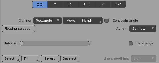
You can select this mode with the M key on the keyboard.
To select a region on the picture, draw a shape around it while keeping down the left button of the mouse. You can set the type of the shape with the menu button next to the Outline: label:
Rectangle - a rectangle with its diagonal,
Ellipse - an ellipse with its diagonal,
Polygon - a polygon, use the Space key to add breakpoints,
Freehand - a freehand outline,
Edges - a freehand outline, but the line sticks to the picture elements and follows their outline,
Rays - projects the existing picture elements radially outwards from the mouse pointer,
Flood - flood fills the similar color parts starting from the mouse pointer.
You can read a more detailed description about these below at the outline tool, where these same shapes can be used for drawing.
The program shows the selected area with “marching ants” outline. The selection behaves as a mask, you can draw only inside of it.
If you activate the Move toggle button, you can move the selected area by clicking on the picture and moving the mouse with pressed button.
With the Morph toggle button you can deform the contents of the selection. By default the deformation translates the contents of the picture, but there are other possibilities, for which use the X and H keys to mark a center point on the picture. After that, in case of X used, you can rotate and scale around the center, and you can shear when it was H. To clear the center mark, move the mouse outside of the picture and press either the X or H keys on the keyboard. You can use Ctrl+Delete for clearing too, regardless of the mouse position.
In deformation modes the transparency of the selected drawing color (the Alpha: slider) defines the elasticity of the effect.
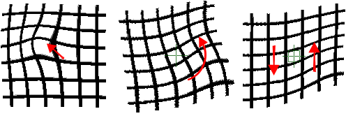
The Morph button has an option menu to store the current deformation to a morph item. You can create a new one or you can superpose the current deformation to an already existing morph item. You can enter the created morph item into the exposure sheet, to deform the contents of other levels with it.
To capture the deformation, enter a name manually to the Item: field at the right side, do not use the right side list because that way it switches to the other picture. The menu items of the button:
Capture morph - creates a morph item with the given name from the current deformation,
Mix to morph - adds the current deformation to the displacement map of the morph item given with the name, but only if its resolution is the same as the edited picture's, otherwise overwrites it,
Load morph - loads a displacement map from a file and distorts the selection with it,
Save morph - saves the current deformation as a displacement map to a file,
Opposite morph - calculates the reversal, opposite transformation of the current deformation. Applying the opposite distortion on the distorted image results the original image (as it is possible),
Relaxation - when you heavily distort a picture, the result can be jagged or fractured. This function smooths out these parts.
The Constrain angle switch restricts the moves to horizontal or vertical directions.
If you activate the Floating selection button, the selection moves together with the transformations and during this, the content behind remains untouched. Otherwise only the contents move and the selection (the “marching ants”) remains in its place.
With the menu of Action: menu, you can define how to add a new selection to the existing selection:
Set new - deletes the old selection and creates the new selection,
Add - adds the new selection to the old one,
Subtract - the new selection erases from the old,
Intersect - the common part of the old and new selections remains, others get deleted.
Use the Unfocus: slider to draw selections with blurred edges. Sometimes it is better to draw the selection without anti-aliasing, without the partially transparent pixels around the edges. Enable this mode with the Hard edge switch.
With the Select button you can create a selection from the current contents of the picture. There is an optional menu to choose the selection mode:
By Alpha - converts the transparency of the picture content into selection, this is the default,
By same color - selects pixels matching to the selected drawing color, it evaluates the visible layers individually, so coverage does not matter,
By merged colors - selects pixels matching to the selected drawing color, using the merged result of the picture sublayers,
By same palette - selects pixels with the same palette as the selected drawing color, or all RGBA pixels if the selected one is a direct RGBA color,
Interlace rows - selects each second pixel rows of the picture, regardless of the picture contents.
If you press Ctrl+Left mouse button, Middle mouse button on the keyboard while selecting these menu items, the mask will be created from the selected picture sublayer only, otherwise all enabled sublayers will be evaluated.
You can repeat the last Select operation with the B key.
The Fill button fills the selection with the selected drawing color. You can do this from the keyboard with V. This button has a menu as well, to perform “select then fill” type operations easily, even on multiple pictures:
Fill with color - fills the current selection with the current color,
Erase to transparent - erases the current selection to transparent,
Select and fill, Select and erase - selects with the last used selection mode, merges it into the existing selection by the Action: mode, then fills or erases. For image sequences, it processes each pictures individually, without merging their selections together.
Select, invert and fill, Select, invert and erase - like the previous mode, but it uses the inverse area of the latest selection mode for making the selection.
In this latter modes with selections, after the operation, the new selection becomes active only if you process the currently edited picture. For an image sequence, the selection from before the operation - if there was any - remains active.
In these fill modes the disabled or partially disabled picture sublayers are not participating in the area selection, but (unlike in other drawing modes) this function fills the selected area in a disabled sublayer too. So by (partially) disabling the target sublayer, it is possible to select and fill an area if the target sublayer contain some content that would disturb the selection.
The Invert button inverts the selection and the Deselect button clears it. You can use the I and C keys to do it as well. The keyboard commands are also available when another drawing mode is active.
The Line smoothing: menu button at the right bottom corner is active when the selected shape is Freehand or Edges. This filter smooths out the bumps of the line when drawing the shape:
None - no line smoothing, the line follows precisely the movements of the mouse pointer,
Light, Medium, Heavy - levels of smoothing. The stronger the smoothing, the less accurately the line follows the mouse and the more it lags behind while drawing.
Color picker mode:
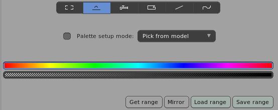
You can select this mode with the P key on the keyboard.
In this mode you can pick a color from the picture into the selected color button. If you click on a palette color, the viewing switches to palette color mode and the left hand side lists displays the palette and the selected palette color. If you click on an RGBA color, you can see the RGBA values. From the keyboard, you can use G to pick a color, even in other drawing modes.
If the palette editing is not disabled otherwise, the Palette setup mode: switch enables a mode where you can define the color of the palette elements. You can read more about this in Chapter 7.2.3.
The two long bars with the color gradients are two color ranges. In other drawing modes you can find a Use color range option, with which you can draw with the selected color range instead of the drawing color.
You can define a color range from the picture if you select a part of the picture with the selection tool and click on the Get range button. It copies the colors of the selection into the range along the horizontal or vertical direction, whichever is longer.
Reversing the order of colors is possible by using the Mirror button, and you can use Load range and Save range buttons to save color ranges to files and to load them back.
Flood fill mode:
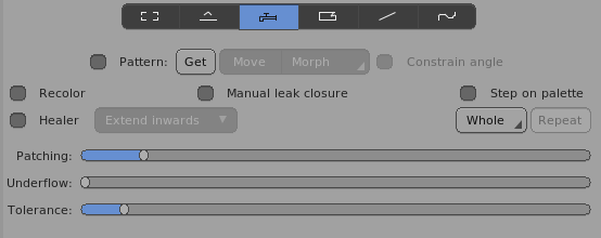
You can select this mode with the F key on the keyboard.
In this mode, when you click on the picture, the clicked area will be filled to its closed borders. As borders the program takes into account the current sublayer and the sublayers above it, the sublayers below have no effect on the result.
You can draw a rectangle on the picture, then within this rectangle, the program fills all closed areas that have the same color as the Target color: button. Since the picture sublayers above are also participate in the fill operation, the program uses the colors of the last single-point fill operation for these. It is the transparent color by default as you usually paint behind a lineart drawing that has transparent background. But if you fill behind something opaque, the following rectangle fills will also fill behind the same overlapping color of the another sublayer. If you want to change this behaviour, fill something with a single click, afterwards the colors at the clicked point will be used for the rectangle fill mode.
If the border is not closed perfectly, the paint leaks through the gap. You can close these holes by hand if you click and draw closing lines on the picture while pressing Shift and Control keys together. After the mouse button released, the program recalculates the fill, so by repeating this operation, sooner or later you will be able to close all the gaps where the paint leaks.
You can draw these closing lines even without the Shift and Control keys if you click the starting point of the line in the immediate vicinity of the painted part outline. If the outline is very porous, it is recommended to switch the Manual leak closure on, then the default action will be the closing of paint leaks, without the need to press Shift and Control. Moreover, in this mode you can use Shift and Control to start a new fill.
A pattern texture can be created from the current picture content by clicking on the Get button next to the Pattern: switch. If there is a selection, the program copies only the contents of the selection. After that, if the Pattern: switch is on, you can fill with the pattern instead of the selected drawing color. If you paint with a pattern, you can also use the Move and Morph buttons. The operation of these buttons is the same as described in the selection mode. For example, you can deform the painted textures manually to follow the movement of the character's body parts or clothes.
The Constrain angle switch is also similar to the same function of the other tools, it restricts the transformations into horizontal or vertical directions only.
In the Recolor mode you can paint over parts that are not transparent. In this mode only the color changes, the original transparency of the picture remains.
As mentioned above, the Manual leak closure enables the drawing of leak closing contours, instead of starting a new fill whenever you click on the picture after a fill. You can switch this option on and off by using the R on the keyboard.
When the Healer option is on, the program will not paint with the drawing color, but instead, it fills each closed outlines with the neighbouring colors. This can be used to eliminate unpainted gaps caused by thick outlines or sharp outline corners. There are different methods available, selected by the menu button to the right of the enabling switch:
Extend inwards - the program extends adjacent colors around the gap towards the inside of the area to be painted,
Dominant color - the whole area will be filled with the single most common adjacent color of the area, palette colors have priority over RGBA colors,
Gradient - the program fills with horizontal and vertical color gradients between the opposite sides of the gap. It works best with RGBA colors, when the gap is surrounded by smooth color gradients.
In this healer mode the Patching: slider has no effect, and the Underflow: is working a bit differently. When it is set, the healing can freely extend over the surroundings of the painted patch, so if there is some border noise around the area to be healed, it can be healed too.
With the Step on palette, after each fill the selection on the palette steps to the next color. It can be useful if you have the same repeating color pattern to fill on several drawings (like squares on a checkered blanket, for example).
There are also two buttons here. The Whole selects the entire picture as a rectangle just like it was selected manually, and uses the fill operation on this rectangle. The Repeat button uses the last fill position or rectangle again. It can repeat the fill operation only if the pixel resolution of the picture is the same as used before. Both buttons are capable to apply the fill operation on a sequence of selected pictures.
The program is able to close small gaps on the outline on its own if you increase the value of the Patching: slider. But it also lowers the accuracy of the painting.
With the Underflow: parameter, you can set a pixel distance to flow behind the contents of the higher sublayers.
The Tolerance: value specifies how far the color of the filled part may differ so that the program can detect it as background color or closing outline.
Outline drawing mode:
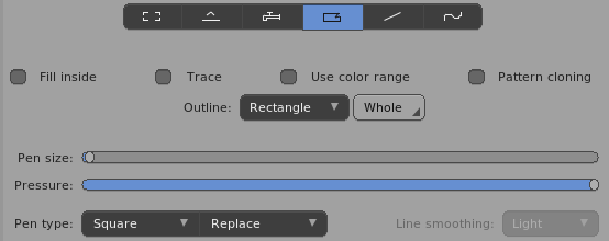
You can select this mode with the O key on the keyboard.
In this mode you can draw shapes manually. To fill the inside of the shape with the selected color, enable the Fill inside switch. Without this the program will draw only outlines.
If you enable the Trace mode, the contents of the current and higher sublayers will modulate the strength of the drawing pen. The pen will trace the existing picture contents.
With the Use color range switch you can draw with the color range selected at the color picker tool. It translates the transparency of the drawing to the colors of the color range. This option can be used only in some specific modes, like Replace, Above, Behind etc.
If you defined a pattern texture at the fill tool, you can use the same pattern for the drawing, if you switch Pattern cloning on. This option can be used only in some specific modes, like Replace, Above, Behind etc.
The Use color range and Pattern cloning options are not usable together, so switching on one of them will switch off the other automatically.
With the Outline: menu you can select the shape to draw. You can use these same shape types to select areas in the selection tool.
Rectangle - draws a rectangle with its diagonal, with Shift it draws a square, with Control the starting point will be the center of the rectangle.
Ellipse - draws an ellipse with the diagonal of its bounding rectangle, with Shift it draws a regular circle, with Control the starting point will be the center of the ellipse.
Polygon - draws a polygon. Click on the picture and drag the mouse with pressed button. Use the Space button to add breakpoints. The program connects the breakpoints with straight lines and also closes the shape. Release the mouse button to finish the shape.
Freehand - freehand drawn line. You can draw a continuous outline curve. The program closes the shape with a straight line between the start and end points.
Edges - freehand drawn line, but the line sticks to the existing picture elements nearby, and follows their outline.
Rays - it extends the existing picture elements radially outwards from the position of the mouse pointer, as if they cast a shadow. For example, this is useful to draw light beams.
Flood - it is similar to the fill tool. It fills the same color parts under the mouse pointer.
The effect of the Whole button is the same as if the whole picture is being drawn as a rectangle. This operation can be executed with the Ctrl+W key. This button also has a menu, where the effect of the Use the same pen menu item is the same to pressing the button. The other menu item, Pen transition is available only if at least two items are selected together on the right hand side list, because this operation is available only for image sequences. The menu item launches the “Pen transition” window. This window can be opened also with the Shift+Ctrl+W key from the keyboard.
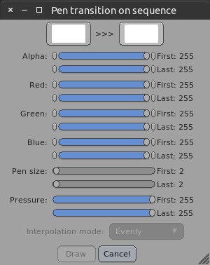
In this window you can set a transition between two drawing colors and between two pen size and pen pressure values. On the sequence of pictures, the drawing of the whole picture is performed with a smooth transition between the first and last values. The curve of the transition can be set with the Interpolation mode: menu:
Evenly - equal steps between the start and end values,
Ease in - starts slow and ends fast,
Ease out - starts fast and slows down,
Ease in/out - speeds up until the middle, then slows down to the end.
You can run the drawing operation with the Draw button, it also closes the pen transition window.
Returning to the drawing window, the content of its bottom part is common for the outline drawing, the line drawing, and the freehand drawing. The pen style and the drawing mode can be set here.
You can set the drawing pen size with Pen size: slider.
You can give the strength of the pen with the Pressure: slider. It's effect is similar to the Alpha: setting of the color, but some pen types are applying it differently.
In the Pen type: menu you can find different pen types.
Square, Round - these pens have a hard edge and without antialiasing,
Smooth - a round pen with antialiased edge and sub-pixel positioning,
Fuzzy - a round fuzzy pen, also antialiased,
Conical - a round fuzzy pen, but the gradient between its center and its edge is linear, usable for gradient effects between adjacent colors,
Chalk, Dry brush, Airbrush ... - these are more other pens to imitate drawing tools and drawing styles.
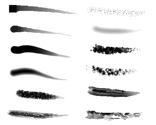
The second menu button of the pen type section is defining the drawing mode:
Replace - replaces the contents of the picture with the pen color, it replaces the transparency as well.
Above - draws over the contents. The pen covers the contents, the transparent parts becomes more opaque.
Behind - similar to the Above mode, but the order of the pen and the previous content is reversed, so it draws behind the contents, into its transparent parts.
Recolor - draws onto the contents. It changes only the color tint, keeps the original transparency.
Remap - only for palette colors, it replaces the palette of the content into the palette of the selected color but keeps the color index inside the palette. If the Target color: is a palette color, it changes only the colors from the given palette. If the Target color: color and the selected color are on the same palette, this mode offsets the index on the palette with the distance between the two indices.
Eraser - this mode uses only the Alpha: component of the selected color for the strength of the eraser. It makes the pixels more transparent but keeps their color tint.
Chroma key - changes the selected color to the color of the Target color: button on the picture. The tint of the selected color represents the color to find, and its Alpha: component represents the tolerance for accepting similar colors.
Alpha cut - this mode uses only the transparency of the selected color and it modifies the transparency only. If the transparency of the picture content is below the given Alpha: value, the pixel turns to transparent, otherwise it remains intact.
Hard cut - the pixel value turns to fully transparent if its transparency is below the given Alpha: value, otherwise it becomes fully opaque.
Gamma - all components of the selected color (Alpha:, Red:, Green:, Blue:) modifies their corresponding components. It changes the transition curve betwen the minimum (0) and maximum (255) values of the components. The new value of the middle (128) can be given, e.g. if a component is 128, that component remains intact.
Overlay - this mode increases or decreases the brigthness of the color components. For a component (Red, Green, Blue) under 128 it darkens, over 128 it brightens the contents. If a component value of the drawing color is 128, the corresponding color component won't change. It changes mostly the mid-level colors, the color component won't change if its original value was either 0 or 255.
Hue - this mode changes only the color hue of the pixels to match with the selected color, but it keeps the original transparency and brightness.
Sharpness - in this only the Alpha: component from the selected color has effect. Under 128 it slightly blurs the contents of the picture, and over 128 it sharpens the picture.
Thickness - this mode uses only the Alpha: component from the selected color. Under 128 it makes the contents thinner and over 128 it thickens. This mode changes the thickness by at most one pixel only. Because of this, this mode is mostly useful for fine tuning the line thickness of lineart drawings. For a bigger change, it's better to use the Trace mode.
Smudge - this mode mixes and blurs the pixels of the picture content. The selected color has no effect in this mode. With the value of the Pressure slider you can change the strength of the smudge effect.
Clone - Copying the contents of the picture. This mode uses the same origin point as the selection and fill tools for the deformation. So you can set the starting point of the cloning with the X or H keys from the keyboard. After you clicked somewhere on the picture, the program copies the contents of the picture from the origin point into the area under the mouse. In this mode, by switching the Pattern cloning on, you can use the texture defined in the fill mode for drawing too.
The Line smoothing: menu button is active when the selected shape is Freehand or Edges. This filter smooths out the bumps of the line when drawing the shape:
None - no line smoothing, the line follows precisely the movements of the mouse pointer,
Light, Medium, Heavy - levels of smoothing. The stronger the smoothing, the less accurately the line follows the mouse and the more it lags behind while drawing.
If it is available, you can use the Shader menu button to execute user defined shader scripts on the picture. Shader scripts are user written complex programs to manipulate and translate colors and perform special drawing operations on a picture. It also can be used on multiple selected pictures at once. If there is no shader script available, this button will be entirely missing. Read how to write these scripts at Appendix C.
Line drawing mode:
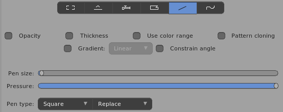
You can select this mode with the L key on the keyboard.
To draw straight lines, click on the picture and move the mouse with pressed button. With the Opacity switch the transparency of the pen will fade into invisible between the starting and end point of the line. Similarly, the Thickness switch decreases the size of the pen to zero along the line.
With the Use color range switch you can draw with the color range selected at the color picker tool. It translates the transparency of the drawing to the colors of the color range. This option can be used only in some specific modes, like Replace, Above, Behind etc.
By switching Pattern cloning on, you can use the texture defined at the fill tool for drawing. This option can be used only in some specific modes, like Replace, Above, Behind etc.
The Use color range and Pattern cloning options are not usable together, so switching on one of them will switch off the other automatically.
To draw color gradients instead of lines, use the Gradient: switch. The gradient fades the selected color into transparent, while keeps the color hue.
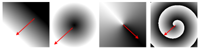
The gradients can be:
Linear - linear gradient, the color fades into transparent between the start and end points,
Radial - central radial gradient, the color fades into transparent between the start point and the ellipse defined by the end point,
Conical - the gradient turns around the start point, the direction of the end point defines the rotation angle,
Spiral - the gradient has a spiral shape around the start point, the distance of the end point gives the elevation of the spiral threads, and its direction defines the rotation angle.
You can use the Constrain angle switch to align the line or the gradient to the horizontal or vertical axes. The Shift key can activate this mode during the drawing. By pressing the Ctrl key, the aligning directions will have a smaller, 15° steps.
The next controls are usable to set the pen type and the drawing mode. These are similar to the settings of the outline and the freehand drawing tool:
Pen size: - defines the size of the drawing pen,
Pressure: - gives the pressure of the pen, which is like a transparency,
Pen type: - has two menus to set the pen type and the drawing mode.
Freehand drawing mode:
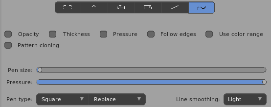
You can select this mode with the D key on the keyboard.
In this mode you can draw lines manually. Click on the picture and move the mouse with its button pressed, along the desired path.
If you have a pressure sensitive pen tablet, enable the pressure control with the Pressure switch. If it is enabled, you can use the Opacity and Thickness switches to specify which parameters should have impact from the pen pressure. By clicking with the Ctrl+Left mouse button, Middle mouse button you can switch these controls only half on. This means the pressure will affect the parameter to a lesser extent.
If the Pressure switch is off, the Opacity and Thickness switches enables to draw continuously fading and thinning lines.
If the Follow edges switch is enabled, and the pen is near to an edge of the undelying content, the pen is sticking to the edge and following it. This mode works similar to the Edges mode at the outline drawing.
With the Use color range switch you can draw with the color range selected at the color picker tool. It translates the transparency of the drawing to the colors of the color range. This option can be used only in some specific modes (Replace, Above, Behind ...).
By switching Pattern cloning on, you can use the texture defined at the fill tool for drawing. This option can be used only in some specific modes (Replace, Above, Behind ...).
The Use color range and Pattern cloning options are not usable together, so switching on one of them will switch off the other automatically.
The Line smoothing: menu button smooths out the bumps of the line while drawing:
None - no line smoothing, the line follows precisely the movements of the mouse pointer,
Light, Medium, Heavy - levels of smoothing. The stronger the smoothing, the less accurately the line follows the mouse and the more it lags behind while drawing.
The next controls are usable to set the pen type and the drawing mode. These are similar to the settings of the outline and the line drawing tool:
Pen size: - defines the size of the drawing pen,
Pressure: - gives the pressure of the pen, which is like a transparency,
Pen type: - has two menus to set the pen type and the drawing mode.
In the drawing mode of the record window, by clicking on the Create... button you can open the window which can be used to make new pictures. With this same window it is possible to copy and resize pictures.
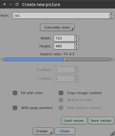
At the top of the window you can enter the name of the new picture item to the Item: input field. When you open the window, this copies the contents of the name field of the record window.
When you press the Calculate sizes button, the program calibrates the new picture according to the current picture and the selection on it. If there is no selection on the drawing, the current size of the picture will be copied into the Width: and Height: fields. But if there is a selection, there can be two modes to calibrate the new picture:
Shrink - the new picture will be cropped to the bounding rectangle of the selection,
Expand - the new picture will relate to the old as the old to the selection. In this mode the new picture will be bigger than the old, there will be an empty frame around the old picture, as large as the frame around the selection in the picture. This sizing mode can be invoked also by clicking on the Calculate sizes button with the Ctrl+Left mouse button, Middle mouse button, without using its menu.
During the calibration the program sets the Width:, Height:, X offset:, Y offset: fields and also the aspect ratio, and sets the switches to copy the picture data.
The Width:, Height: fields and the aspect_ratio slider together describe the geometry of the new picture.
The aspect ratio slider is similar to the one used at the movie settings, with the small rectangles at the ends of the slider, or with its right button menu you can select from standard formats.
The Fixed aspect ratio for outline drawing switch is an additional feature and not related with new picture creation. If it is switched on, and you draw a rectangle or ellipse shape on the picture editor window, its aspect ratio will be the value of the aspect ratio slider in this window.
The Fill with color fills the new picture with the selected drawing color on the selected sublayer, while the Copy image content copies the contents of the current picture. From these two only one can be switched on.
Together with Copy image content, you can use the Stretch to size option to resize the picture content to the given width and height. If this option is off, the pixels of the edited picture will be copied one by one without interpolation.
When With pegs position is on, the new picture will get the pegs position of the current picture, corrected according to the target geometry.
The With picture vectors copies the picture vectors that stored in the current picture,
When Copy image content is on and Stretch to size is off, the X offset: and Y offset: fields are determining the offset of the center of the original picture relative to the center of the new picture, in entire pixels. During copying the picture content, there is no fractional pixel offset, it copies all pixels one in one.
With the Load values button you can load a previously saved settings configuration into this window. With the Save values button, you can save the settings into a file.
After Create button clicked, the program creates the new picture. If the name belongs to an already existing item, it will be overwritten without request. The window does not close after the operation.
When there is a picture sequence selected on the right side list of the record window when the Create pressed, it applies the current operation on all of the selected pictures. This way you can crop existing pictures, change their aspect ratio, you can add or remove pegs positions etc.
The Create button has a menu as well:
This name - captures the given name,
Next - adds one to the numbering of the given name, and captures the new name. This mode can be invoked by clicking with the Ctrl+Left mouse button, Middle mouse button, without using the menu.
You can close the window with the Close button.
In the Firka program the sublayers of pictures can contain palette pixels. A palette color is not containing its color components directly, but it is a reference to an element of the palette, which can have any specific color. The hue of the palette colors can be changed easily, by changing a palette element, the modified color will change on all drawings at once. For painting, you can name and handle the colors of a character according to their function (eyes, hair, clothes etc.).
If you modify a color on a palette, it changes everywhere immediately. The palettes are arranged in a hierarchy. You can assign a palette to the picture sublayer, to the redirectable content of the X-sheet level, to the X-sheet level itself, to the entire exposure sheet, to the scene or to the movie. This is a priority order, the picture sublayer has the highest and the movie has the lowest priority. Every palette has a code number between 0 and 255, and when two palettes have the same code number, the higher priority level overrides the palette on the lower priority level.
For example, a palette with 100 code number in an X-sheet
level overrides the 100 code number palette of the
scene, but only in that specific X-sheet level.
The colors on a movie palette are shared between all scenes of the movie.
If a drawing refers to a non-existent palette entry, the pixel color will be opaque black.
If you click on any of the hierarchy levels (Movie, Scene...) on the list at the top left corner, you can see the associated controls at the bottom left corner.
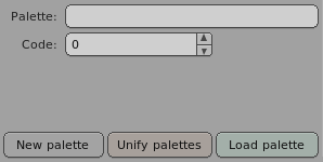
To create a new palette, enter a name into the Palette: field, and enter a code number to the Code: field as well. Then you can create the palette with the New palette button. The name of the palette will appear on the hierarchy list.
You can use the Load palette to load back a previously saved palette as a new palette. Normally the palette file contains its name and code number, so it will be loaded with these parameters. But since it is a plain text file, if somehow these parameters are missing, the program will use the Palette: and Code: fields as defaults. In the file loader window you can select multiple palettes to load them at once.
The Unify palettes button is a complex fuction. From the current picture, or if multiple pictures are selected on the right side list, from those pictures, collects all the used palette colors and makes a unified palette with them. In the selected pictures it also replaces the palette colors to the elements of the new palette. The elements of the new palette will be links to the original palette entries.
After selecting a palette on the hierarchy, you can use the Rename button to rename both the name and the code number for the palette. The Delete button deletes the selected palette.
You can save the palette into a text file with the Save palette button, which can be loaded as a new palette with the Load palette, or if a palette is selected on the top left list, it can be replaced with the contents of the file by using the Update palette button.
By default a new palette contains only one palette entry, a black color without name. You can see it on the bottom list below the hierarchy list on the left side. If you click on it, another new controls become available at the bottom left corner.
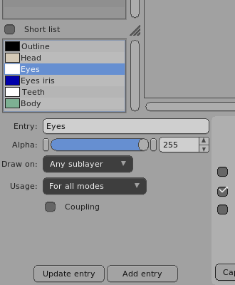
In the Entry: field you can see the name of the selected palette entry, and you can enter the name for a new entry here as well.
The Alpha: field contains the transparency for the drawing or painting operations. This does not belong to the palette entry, but to the pixels to be drawn. Each pixels on the picture have their own transparency values, even when they contain palette colors. However, the color of a palette entry may also contain transparency. In this case the two transparencies together give the final result.
With the Draw on: menu you can set a picture sublayer to be activated automatically when selecting the palette color. This ensures that a given palette color can always be drawn to the picture sublayer that is intended for it. Later it is possible to change the sublayer to another, this works only when selecting a palette color. The possible select modes:
Any sublayer - no sublayer selection, drawing on any sublayers permitted,
1. Generic..level_8 - selects the sublayer for drawing,
Sublayers 1..3 - if one of the 1., 2. or 3. sublayers is already selected (these are typically the outline layers) it remains, otherwise the 3. sublayer will be selected,
Sublayers 4..8 - if one of the sublayers between 4. and 8. is already selected (these are typically the paint layers) it remains, otherwise the 4. sublayer will be selected,
With the Usage: menu, a drawing function can be selected, which will be automatically set up when the palette color selected:
For all modes - no drawing mode selected,
Flood fill - steps into the flood fill painting mode,
Recolor - steps into the outline drawing mode, and selects recoloring,
Fill or recolor - if it is alreasy in fill or recolor mode, it remains there, otherwise steps into the fill mode.
Freehand drawing - steps into the freehand drawing mode.
With the Update entry button you can update the name and these settings in the selected palette color entry. The Add entry button creates a new entry at the end of the palette with the given settings. It is not enabled to insert a new entry between the palette entries, because this would damage the indexing of the already used entries in the existing pictures, instead the new color can be added only to the end of the palette. However, if you need to insert a color, save the palette to a text file with the Save palette button, then edit it in a text editor and replace the palette with the modified version with the Update palette button.
To change the RGBA components of the palette entry, turn the Coupling switch on. Now if you pick a color from the current picture with the color picker tool, or by pressing the G key, the selected color updates the color of the selected palette entry. If you select a palette color this way, the result will be a link to the another palette entry, indicated by a small arrow next to the palette entry name on the list. You can also switch to the RGBA mode to change the color manually, if you switch the Palette colors option off.
You can load a sound into the program with the Load item button on the X-sheet window. The Firka program has no sound digitizer or music editor functions, so sounds must always be loaded from external files.
The sound editor is accessible from the record window. Click on the Sounds tab at the top right corner to reach the sound functions. Then select an existing sound on the side list, then its waveform will appear on the display area.
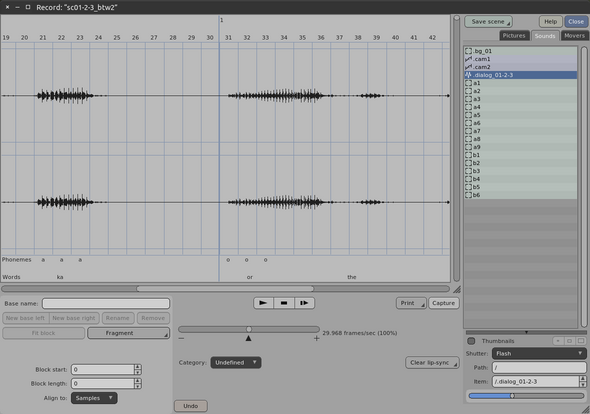
You can select a part of the sound when click on the waveform and drag the mouse with pressed button. The selected part can be played with the playing buttons under the waveform field. You can play the sound faster or slower with the slider under the playing buttons, in a similar way how it works in the player window.
From the keyboard you can use the P, Return/Enter key to play the sound or the selected part, and the Space, Insert button to continue from the current position, or to stop playing.
If you click on an existing selection near to its border edges, you can replace the edge, otherwise clicking elsewhere, you will start a new selection. The position and size of the selection can be set as numbers with the Block start: and Block length: input fields. You can set the measuring unit for the positions with the Align to: menu:
Samples - the smallest unit of the sound, the individual sound sample will be the unit of the alignment. The resolution will be determined by the sampling frequency of the sound. For example if it is 44 kHz, then the sound will be split to 44000 units per second.
Frames - it will use frame accuracy according to the play speed of the movie.
Seconds - it will align to seconds.
This setting determines the alignment of the selection edges, for example with frame accuracy, the selection will start and end on a frame boundary.
You can use the Numpad-1 ... Numpad-9 numbers on the numeric keyboard, to zoom into the sound. If the mouse pointer is over the display area, it zooms to the pointer's position, otherwise it zooms to the center. With the Plus (+) and Minus (-) keys you can zoom in and out step by step. The mouse wheel is also able to zoom when the mouse pointer is over the waveform field, and the slider at the bottom right corner of the window also can be used for zooming.
On the waveform there is a grid which shows seconds or frames, depending on the zooming level.
The sound waves themselves can be magnified with the vertical scrollbar next to the waveform field. In other modes this is usable for vertical scrolling, but in case of sounds, the amplitude of the waveform can be enlarged, in order to better visualize the quiet sounds too.
Dialog breaking down:
Under the waveform, inside of the display, if the zooming is big enough, two labels can be visible, Phonemes and Words. You can enter the breaking down (also called lip sync) into these rows. This is an important aid for animators, especially for making mouth movements. Sounds, as temporal things, are independent of the play speed of the movies. Therefore the entered breaking down of the sound is also connected to the own timeline of the sound. If it turns out later that the play speed is different from the one was used for the breaking down, the breaking down data very likely still remain usable.
After you clicked on one of the two horizontal rows, you can enter letter marks from the keyboard to the selected position. Use short words only (up to five characters) and split the long words into smaller fragmens. To change an existing label click on the text, it will appear in the text field and can be rewritten. While entering, use the Up and Down arrow keys to move the entering position forwards or backwards in the sound by one frame. If there is a text already in the new position, it will show up automatically in the input field.
The Tab key plays the cca. 1/10 second area around the entering position, this helps to find the exact position of the phonemes.
With the Capture button you can store the selected part of the sound under the name entered into the Item: field.
Use the Print button to print the sound together with the entered phonemes and words. With the menu of the button you can select how many rows to be printed on a page (50 or 100).
With the Clear lip-sync button you can clear the contents of the Phonemes or Words rows. With the menu of this button you can select that you want both of them or only one row to be cleared.
Marking specific positions on the sound:
You can mark a position of the sound with a name entered to the Base
name: field. This base position can be used as a starting
reference in the exposure sheet. To use it, enter a slash ( /
) character and the name of the marker after the name of the
sound in the X-sheet.
The New base left button marks the sound at the beginning of the selected range, while the New base right marks the end position of the range. The marked base will be represented by a vertical bar and its name at top, over the waveform. The position can be replaced by click and drag with pressed left mouse button. If you want to select the base only without moving it, use Ctrl+Left mouse button, Middle mouse button.
The selected base can be renamed with the Rename button, and you can delete it with the Remove button. With the Fit block button you can extend the edges of the existing selection to the nearest bases.
The Fragment button can be used to split a sound into a sequence of fragments automatically, for example when you want to split the received sound into scenes. In the menu there are two possible modes:
At base points - splits the sound at the base points, the fragmented parts will get the names of the base positions,
By timecode list - it will work by a time code list, loaded from an external file. You can export such a list from the Playlist window from the scene list that you arranged there.
With the button next to the Category: label you can select the category of the sound. This can be used to disable the sound playback by category at the settings of the player window:
Undefined - the default, undefined type,
Dialog, Music, Sound fx - soundtrack types, these can be enabled or disabled during playing.
You can use the Undo button to undo the last changes of the selected sound. The undo operation affects only the actually selected item.
In a traditional linetest, the camera operator takes the pictures at their final position, according to the field chart. In this case there is no camera movement, or the camera movements are made by repositioning the drawings under the camera.
Sometimes, when there are large background movements in the scene, this can be difficult. In the Firka program, it is possible to move drawings (more precisely the X-sheet levels containing them) with programmatically calculated motion paths.
When calulating the position of a layer, the program first place the picture according to the pegbar position of the layer, then it goes through the levels in order from the bottom level and changes this position with the motion paths that applied on the level. In the program any number of movers can be summed up to move a level.
For examople, if in a finished scene you want to change the entire
field frame, then you can easily enter an additional mover into the
topmost level of the X-sheet, which affects all of the levels (level
group name: All ). This will work because of summation of
the movers, even if there are other movers on the lower levels.
The movers affect the X and Y axes of the level contents equally, so the two axes remain always perpendicular and the proportions of the picture remain unchanged. But there is an X-sheet level type, with which this can be changed, it is the Deformation path level. The movers entered into this level will behave differently, the level can be stretched in the direction of the size vector, by the value of its length, and the level can be skewed by the coordinate components of the base point vector.
The mover window is reachable through the Record button on the X-sheet window, just like the camera capture. The Movers tab should be selected at the upper right corner of the window for the mover editor mode.
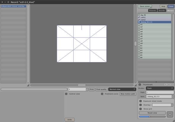
A list can be seen at the left side of the window, and on the big workspace there is a white rectangle on a gray background. This rectangle represents the camera field.
To make a new mover, click on the workspace, and move the mouse with pressed down button. This way a new segment can be made, a straight line between two endpoints. This mover path is not stored yet, it is in a temporary storage, the program shows it in the list on the left with Independent mover overlay name.
If you switch the Freehand curve option on before creating the mover path, you will be able to draw a freehand path with the mouse instead of a single straight line.
You can use the Numpad-1 ... Numpad-9 numbers on the numeric keyboard, to set the zoom for the display. If the mouse pointer is over the picture, it zooms to the pointer's position, otherwise it zooms to the center. With the Plus (+) and Minus (-) keys you can zoom in and out step by step. The mouse wheel is also usable for zooming when the mouse pointer is over the picture field.
Additionally, you can use the zoom slider and the positioning tool at the right bottom corner of the window, or the scrollbars around the picture field. With the arrow keys on the keyboard, you can move the visible area. If you click on the picture with the Ctrl+Left mouse button, Right mouse button, Ctrl+Middle mouse button and drag the mouse with pressed button, you can increase (by dragging down) or decrease the zooming (by dragging up). If you drag the mouse on the picture with the Shift+Left mouse button, Middle mouse button, Shift+Middle mouse button, you can change the location of the visible area.
With the Central view view switch, the displaying of the path becomes different and you can follow how the camera field moves along the path. In this mode the current point is always at the center of the field.
To save the created path, enter a name to the Item: field and click on the Capture button. You can see that a new image name appears on the right side list. You can also create the item if you press the Return/Enter key after you entered the name in the Item: field.
You can clear the contents of the overlay mover by using the Clear button.
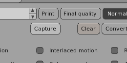
When you click on a mover item on the right side list, on the left side the Independent mover overlay name becomes Mover overlay:, followed by the name of the selected item. Now you can edit the selected item directly. If you want to edit its content independently without modifying the actual item, the Overlay alone button makes a copy of the content and goes back to the Independent mover overlay mode to edit it alone.
When clicking on the line between the two points, the segment will be selected, and also a cross mark appears at the point selected by the click. Then new control elements appear at the bottom left corner of the window.
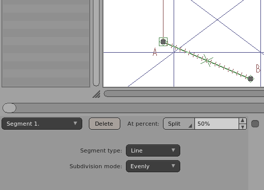
You can use the menu at the left to select segments and path points. With the Delete button you can delete the selected segment. The segment can be bisected with a new breakpoint at the selected position with Split button. The button also has a menu, where you can set the key and fixed state for the new point instantly. In the At percent: field you can enter the location of the selected position within the segment numerically.
The J key selects the segment of the current frame position, and also sets the percentage value for it.
With the menu next to the Segment type: label you can specify the type of the segment:
Line - straight line between two points,
Arc - regular circle arc, the radius can be given numerically in the Radius: field. The Complementer arc switch can be used to switch between the arc and its complementer arc.
Spline - Bezier spline with two control points.
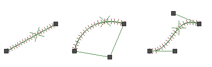
If the segment type is Line, only the two endpoints are moveable.
If the segment is an Arc, then when you click on the segment, the center point of the arc becomes visible, which is moveable.
If the segment is a Spline, after the segment selected, the two control points appear, with which you can change the shape of the curve. By moving the control point with Ctrl+Left mouse button, Right mouse button, if the neighbour segment is also a Spline, the two connecting points will move together in the same straight line. If the other segment is Line or Arc, the direction of the control point will be aligned to the direction of the neighbour. With this, the curve will be break-free at the point.
Use the menu button next to the Subdivision mode: label to set how to divide the selected segment into positions of the motion. This effects how the location, size and rotation of the camera positions will be calculated:
Evenly - this is the default behaviour, a linear interpolation.
Ease in - the motion starts still and speeds up until the endpoint,
Ease out - the motion slows down to zero speed until the endpoint,
Ease in/out - the motion speeds up, then slows down between the endpoints.
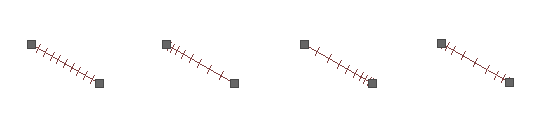
If you select a point instead of a segment, the controls will be different.
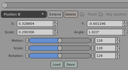
If the selected point is one of the two open ends of the curve, the curve can be extended with a new segment and a new endpoint by using the Extend button.
The Delete button deletes the point.
If the Fixed switch is on, the point will remain in place when a neighbour point gets moved. Otherwise the point will move proportionally to keep the shape of the curve which going through it. On the motion path, the fixed state of a point is represented by a small rhombus shape around its position.
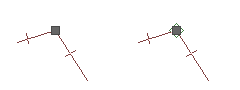
With the Key position switch, you can mark any point as a key position. These positions can be entered into the exposure sheet. You can specify movements between the key positions in the X-sheet, and the motion can be stopped only on these points.
The labels are letters from the alphabet, from A to
P and they come in a strict sequence on the curve, they
cannot be switched. The point A is always the first
point of the total path.
The values in X: and Y: fields are the base point, and the Scale: and Angle: are the size vector. The unit of the size values is the half height of the camera field, and the rotation angle is given in degrees.
In these input fields you can specify the values for the current point
numerically. It is also possible to use basic numeric calculations.
You can add ( + ), subtract ( - ), multiply
( * ) or divide ( / ) numbers. As the first
element of the expression, you can reference the value of an existing
point, even from the path of another mover item.
Some examples of the expressions you can type:
1
the value of 1,
1+1
calculate the value of 1 + 1,
x
the value of the X: field of the current point,
y
the value of the Y: field of the current point,
s
the value of the Scale: field of the current point,
r
the value of the Angle: field of the current point,
a
the value of the similar field from key point A on the
current motion path,
bx
the value of the X: field of key point B on the
current motion path.
cam1/cy+1
add 1 to the value of the Y: field of key point C
from the “cam1” mover item.
You can use these expressions only to calculate constant numeric values easier. It is not possible to keep permanent relations between the points this way.
For every points, the Motion:, Scale:, and Rotation: speed parameters can be set. The speeds are relative values to the speeds of the other points. For example if a value of one point is 100, and 50 for the other, then at the point of 100, the speed will be twice as much as the speed at the point of 50. The small transversal lines drawn on the curve represent the positions on the frames of the motion.
If the division mode of the segment is other than Evenly, the speed values are still usable to adjust the speed of the motion. For examle, in Ease in mode, the motion basically will start from still and speed up until the endpoint, but the exact speed change along the motion path can be manipulated with the speed values of the endpoints.
To move the selected point, click on the small rectangle at the point with the mouse and drag it. You can click with the Ctrl+Left mouse button, Right mouse button to move all points together, and Shift+Left mouse button, Middle mouse button only selects the point without moving it.
From the selected point a T shape handle reaches out, with a movable point at the end. This is the vector of the size and rotation, these parameters can be changed by moving this point. With the Ctrl+Left mouse button, Right mouse button you can resize the size vector without rotating it, and with Shift+Left mouse button, Middle mouse button you can rotate it only, without sizing.
You can screw the handle around the base point several times, if you want to set a rotation higher than 360 degrees. This has a reason if something have to rotate more than a full circle between two points.
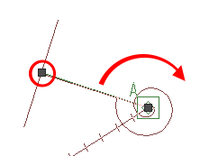
The Firka program can operate with two main types of movers. The type discussed previously is the more often used type, when the motion path consists of breakpoints and segments, mathematical curves between them.
The other type of mover is a sequence of frame positions, when all points are defined by two vectors (the base point and the size vector). With this you can set individual positions for all of the frames during the movement.
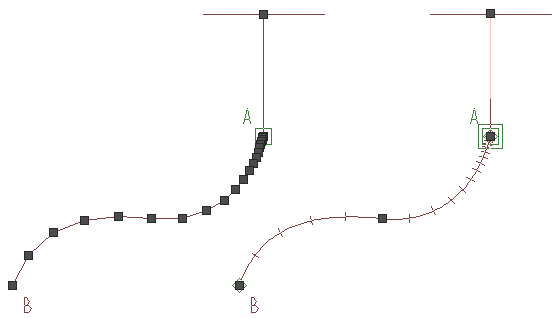
You can convert the motion path into the point sequence type with the Convert to points button.
With a point sequence, the Insert, Extend and Delete buttons are usable to add and delete points. The key positions can be set for this motion type too.
The following settings are not belong to individual points or segments, but to the mover itself:
If you use pan and zoom together, there is a problem which well known in compositiong: the visible speed of the motion depends on the scale of the picture field, so a constant speed movement seems accelerating. And even the evenly spaced zooming seems to be accelerating.
To avoid this effect, use the Balanced motion switch to equalize the speed of the motion, and the Balanced scale switch to balance the speed of zooming. Generally it's better to use these together.
The rotation can follow the direction of the motion path curve if you switch Relative rotation on. For example, if a car moved on a road, the front of the car will be always on the direction of the motion, so the rotation of the car will follow the path.
Normally the paths move the pictures and not the camera field, but on the field guides, usually the path of the camera field given, over the background picture. To make these informations usable, you can switch the Field motion motion on. Then you can align the points of the motion curve onto the positions and fields shown on the layout, and if a mover made this way, the field will move according to the given path.
It is possible to render a scene in interlaced mode, if the goal is to make an interlaced video. In this case every second row of the picture will be shifted in time by half frame. The Interlaced motion switch enables the use of this time offset in the calculations for these half frames. This switch has effect only when rendering to file, and only if the selected format of the file is interlaced.
The Apply 3D switch enables the moving of the levels according to their 3D Z depth for the motion path. Otherwise all levels will be moved equally in the plane. If it takes the 3D depth into consideration, the distant levels will be moved to a proportionally lesser extent, according to the laws of perspective.
With the window that can be opened by the Pan & Scan button, if a movie has to be rendered in two different image field formats, for example there is a widescreen and a 4:3 version, you can set what extent you want the mover to effect when using these field formats.
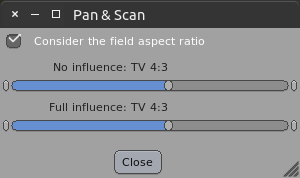
In the window you can enable the field shape awareness with switching the Consider the field aspect ratio on.
With the No influence: slider you can set the field aspect ratio for which the mover will have no effect at all.
And with the Full influence: slider the field aspect ratio can be set for which the mover will effect in its original form. If the field format differs from both of the given values the program will interpolate the result, the effect of the mover vill only be partial.
In every mode, with the Undo button, you can undo the last positioning operations, such as edits of mover paths and position changes of pegbars and pictures. The U, Esc, Ctrl+U, Ctrl+Z keys are also usable for the same. The undo operation affects only the actually selected components, ie. restores the displayed pegbar, mover or picture/morph item.
The origin of the coordinate system, the (X,Y) = (0,0) point is the center of the projecting image field. The positive direction of the horizontal X axis goes from this to the right, and the positive direction of the vertical Y axis goes upwards. The scales of the two axes are the same.
The unit of the coordinate system is the half of the vertical size of the projection image field. So the top edge of the field is on the Y=1, the bottom edge is on the Y=-1 coordinates. The left and right edge of the field depends on the aspect ratio of the chosen image field.
A motion position consists of two vectors. The first vector is the location of the base point (pivot) of the picture from the origin, the second is a size vector, which defines the scale and rotation of the picture. This latter size vector defines the position of the top edge midpoint of the picture, relative to the base point. If the length of the size vector is 1, the vertical size of the picture will be 2 units, so its size will match to the vertical size of the projection image field. The length of the size vector defines the scale value, and its direction defines the rotation angle.
Some examples:
- a picture fills exactly the image field vertically:
base point: (0,0) size vector: (0,1) length: 1 rotation 0°,
- the same picture, rotated by 90 degrees clockwise:
base point: (0,0) size vector: (1,0) length: 1 rotation 90°,
- the first picture, enlarged to its double size:
base point: (0,0) size vector: (0,2) length: 2 rotation 0°,
- the center point of the first picture moved to the bottom edge of the field:
base point: (0,-1) size vector: (0,1) length: 1 rotation 0°.
The movers are items with names, like pictures and sounds. By entering this name to the X-sheet you can move the position of other levels. In the X-sheet the mover moves the levels of the selected level group, just like how effects work. You can read more about the level groups in Chapter 6.7.3.
The format of the movers in the X-sheet is discussed in more detail in Chapter 6.2.3. Shortly: the name of the mover should contain that from which key postion to which the movement lasts. The key positions are marked with letters from A to P.
When the mover is in the X-sheet, you can return to the record window. In the mover view, after switching Exposure sheet mode on, a new field with the level of the cursor of the exposure sheet becomes visible at the left edge of the window. Meanwhile, the levels of the X-sheet appear on the left side list, and the selected frame of the scene becomes visible in the image field. In the scene, movers and pegbar positions and picture positions relative to the pegs can be edited. Use the slider on the bottom part of the window to select the frame of the scene, and use the left side list to select the level you want to edit.
If you double click on a level on the left side list, it opens the properties window of the level.
When the Exposure sheet mode is on and you select an X-sheet level on the left side list that has a pegbar, it will show the figure illustrating the position of the pegpar. Also you can see a similar pegbar when you select the Picture overlay: layer.
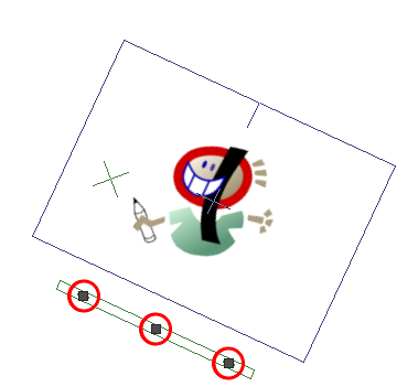
With the three small rectangles on the pegbar, the pegs can be freely replaced, scaled, rotated. There is also an X mark on the picture which shows the current position of the base point, the motion paths are moving this point.
If the level contains a picture, you can see its bounding rectangle as well.
By dragging the side pegs with Ctrl+Left mouse button, Right mouse button, the pegbar will be resized only in its current direction, without rotation.
If you click on the middle peg with Ctrl+Left mouse button, Right mouse button, you can enlarge or shrink the pegbar relative to the base point, without rotation.
Clicking on any of the pegs with Shift+Left mouse button, Middle mouse button turns the pegbar to horizontal or vertical position, whichever is closer to it.
The bottom left part of the window contains the control elements to adjust the pegs position.
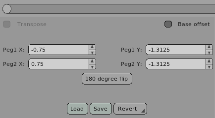
You can also drag the pegbar by clicking anywhere on the display area. With the X key you can place a small + mark on the display at the mouse pointer. If it is there, and you drag the pegbar, the marked position will remain in place and everything will rotate and scale around it. To clear this mark, move the mouse outside of the picture and press X. You can use Ctrl+Delete for this too, regardless of the mouse position.
On the bottom left part of the window you can find the 180 degree flip button. It swaps the two side points of the pegbar, causing the pegbar to rotate by 180 degrees, so the attached drawing goes to its opposite side.
Sometimes a picture can be misplaced relative to its pegs, because of animation reasons or, for example when it was misplaced during scanning. In this case its position can be corrected by switching Transpose on. You can read more about this theme in Chapter 7.4.5.
Firka program works basically on a planar surface, but it is possible to use spatial depth in a simplified manner. The levels can get their Z depth values, which the program can use in the motion path calculations, according to the laws of perspective.
The camera is in the (X,Y,Z) = (0,0,0) point and looks at the point (0,0,1). The picture contents are in the Z=1 plane by default. The levels can be moved away from this in the depth direction, but it affects only the position calculations, the coverage relations are still specified by the level order of the scene. It is still might be wothwile to use this solution, because it suits well for the needs of the traditional solutions in the animation. For complicated cases, it is better to use a 3D program instead.
The scaling of a level, according to the laws of perspective, is 1/Z. If the Z value is larger than 1, the result becomes smaller, between 0 and 1 it enlarges. In Firka the negative values behaves like the positives, but the picture turns upside down. The 0 distance is undefined, and the values near zero are also should be avoided, because of the extreme big scalings. If a level content gets near to zero or in the negative range, it is recommended to enter blank frames into the level for that section.
While the Exposure sheet mode is on, you can select a level on the left side list to set its location in space. You can enter to this mode by clicking on the Level's 3D position button.
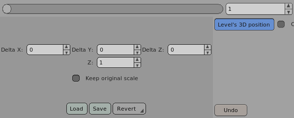
There are four parameters to set the spatial location:
Delta X:, Delta Y:, Delta Z:
- These coordinates are defining the inclination of the picture plane, these are relative coordinates to the base point. The picture plane goes through the base point, and also through this displaced point. When the movers are changing the position of the level, this inclination defines how the level will deform. The deformation is axonometrical, the program does not use real perspective.
Z:
- This is the most important parameter, it defines the distance of the level from the camera. By default this value is 1.
By switching the Keep original scale switch on, the program zooms back the content of the level so its size does not change when its Z coordinate is not 1. Without this, the Z: parameter has effect also on the size of the level content.
If the Exposure sheet mode is enabled, you can relocate the drawings in the exposure sheet relative to their pegs. This means a correction of the pegs position within the picture, so it affects all occurences of the drawing in the X-sheet. It is similar to, when the animator corrects a drawing and cuts off the pegholes part of the paper and pastes it back in a different position.
To use it, switch the Exposure sheet mode on, and select a drawing on the left side list, on a level with a pegbar selected. Then by switching the Transpose on, you can step into the relocating mode.
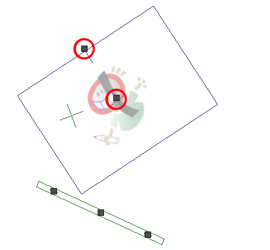
With the small rectangles on the center and on the midpoint of the top edge, you can move, scale and rotate the picture relative to its pegs.
If you drag the midpoint of the top edge with Ctrl+Left mouse button, Right mouse button, the picture will scale only and not rotate.
By clicking on any of the two points with Shift+Left mouse button, Middle mouse button, it aligns the position of the picture to be parallel to its pegbar.
You can also drag the picture by clicking anywhere on the display area. With the X key you can place a small + mark on the display at the mouse pointer. If it is there, and you drag the picture, the marked position will remain in place and everything will rotate and scale around it. To clear this mark, move the mouse outside of the picture and press X. You can use Ctrl+Delete for this too, regardless of the mouse position.
Another solution in the program is using the base offset. This is useful when there is a pegs position which is used on multiple levels and a certain level has a displacement from the original pegs position. For example, there is a character level, and a cast shadow created from the same level in black color, by shifting it to a distance, under the level. In this case the two levels can be on the same pegbar, and the shifted level can be placed with an additional mover or with a base offset. The base offset belongs to the level and it is an addition to the pegbar position of the level.
To set it, you have to select a level on the left side list which has a pegbar position. Then by switching Base offset on, an arrow appears on the screen to set the base point and the size vector. With the two small squares at the two ends of the arrow you can adjust the base offset.
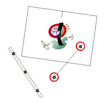
You can scale and rotate with the base offset as well. The base offset can be reset to its original zero position with the Delete key.
The same position corrections are also available for morph items.
In the X-sheet if a picture item happens to be in a mover type level, the program uses these pictures as motion positions, picture vectors. The mover type levels are these:
Light rays effect,
Picture vectors,
Deformation path,
Perspective path,
Mirror path,
3D position.
This can be useful for example, when each picture needs a unique position correction in the X-sheet. In this case a copy of the picture level can be used in the mover type level, ensuring that all pictures will be in pair with their corresponding motion position (which are themselves).
Each picture can have at most eight picture vectors, which corresponds to the eight picture sublayers. The pegbar of the level, and the sublayer combination of the level properties summarized from 1 to 8 in order together give the resulting motion position.
To edit the picture vectors, you should select a mover type level on the left side list. In the level a pegbar should also be selected, because the pegs position of the level will be added to the offset.
In this case the Transpose switch, which is usable to relocate the picture content relative to its pegs, gets a menu button:
Picture content - the original function, to relocate the current picture relative to the pegbar, while the pegbar remaining in place,
Vector 1. Generic .. Vector 8. Spare - to relocate the picture vectors of the current picture.
The picture vector consists of a base position and an assigned size vector. By relocating these you can change the picture vector. A picture vector can be reset to its default position with the Delete key.
To open the player window, click Play button at the top left corner of the exposure sheet window.
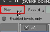
The same window appears when you play concatenated scenes in the Playlist window. At start you can see the frame at the cursor of the exposure sheet in the window. With this window the scene can be played frame-by-frame or continuously.
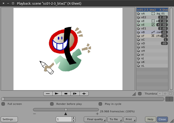
In this window you can find a small sizing rectangle at the right side. If you move it to the left, a list field will appear to the right of the square. If the projection is stopped, the list shows the contents of the levels in the displayed frame. By clicking on a level in the list, the selected level becomes highlighted on the displayed picture. If you click on the list twice the window of the properties of the selected level opens.
The play button (with the triangle icon) starts playing the scene from the first frame of the scene, and the continue button (line and triangle icon) continues it from the current position. You can stop play by clicking the stop button (square icon). After the play stopped you can replace the current frame position by using the long slider bar or by entering the frame number into the numeric input field in the middle of the bottom side of the window. By clicking the little triangular arrows beside the input field you can either increase or decrease the settled number. You can do this also with the mouse wheel if you place the mouse over the input field.
The + and - buttons move the displayed position by one frame forwards or backwards. On the keyboard, the cursor keys serves for the same. You can find the keyboard commands for playing in Appendix A.6. By clicking on these buttons with Ctrl+Left mouse button, Middle mouse button, the displayed position will jump to the next or previous motion step of the current exposure sheet level.
The playing position and the cursor of the exposure sheet are connected. If you are changing the position in the player window, the cursor of the exposure sheet window follows it, so if you place the two windows next to each other, to follow the position in the exposure sheet also. And if you move the cursor of the exposure sheet, the displayed frame also will follow the movement. If you modify something in the exposure sheet, or enable or disable a level, the player window's display will follow these changes immediately.
During play the two small squares on the right hand side of the window will blink if the projection is dropped from the sync. If only the left flashes up, it means the motion step has been played late, but it has not hung down into the next motion step. If both of them flash, it indicates that the program is missed one or more steps during the play.
With the shorter slider bar at the bottom left part of the window, you can increase or decrease the play speed. Clicking the small triangle at the middle of the slider resets the speed to the nominal value. Next to the slider the current speed is viewed.
With Full screen switch you can set the display into full sceen mode. It is possible to configure Firka to view the fullscreen mode on a separate hardware display, by default, however the fullscreen display will go to the same screen on which the playing window is located.
The Render before play switch can be used when a scene is complicated and because of this, the program cannot play it in real time. If you switch it on, it assembles the frames before playing, so the projection has less load on the computer.
If Play in cycle is on, the play restarts from the beginning when it reaches the end of the scene, otherwise the projection stops at the last frame.
The Final quality menu allows you to render a single frame or entire animation in high quality. Final quality rendering can be very slow, therefore this function enables the Render before play option automatically.
With the To file button you can render the current frame into a file. The same can be printed with the Print button.
In the player window, click on the Playback parameters: button to open the player settings window.
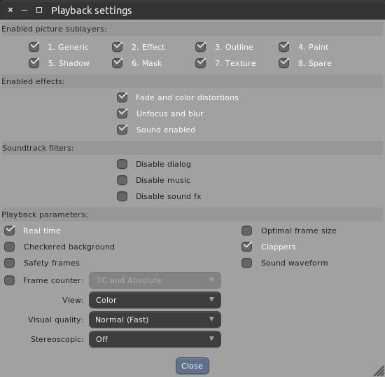
At the Enabled picture sublayers: section, the internal sublayers of the pictures can be enabled or disabled for the entire scene. A picture item can contain eight internal layer types. For example if the painted parts of a figure are located on a separate sublayer, you can turn off the painted parts to make only the contours visible.
At the Enabled effects: section you can disable some effect types globally to increase the speed of display:
Fade and color distortions - This switch disables the rendering of transition and coloring effects (Red, Green, Blue, Alpha).
Unfocus and blur - This switch can disable the unfocus effects. Occasionally, unfocusing may slow down the calculation of frames.
Sound enabled - Disables the sound globally.
In the Soundtrack filters: section you can disable the sounds that have been marked as either dialog, music or effect in the sound editor window.
Disable dialog, Disable music, Disable sound fx - With these switches you can disable the various sound types.
If Real time switch is on, the speed of the play strictly keeps the settled frame rate, even though motion frames have to be dropped because of it. When it is switched off, it projects every frames, even if the projection slows down because of this. This can lead to the meowing of the sound because the sound tries to follow the speed of the picture.
The Optimal frame size switch settles the displayed picture in a way that every pixel will be visible, but the picture shall be enlarged to the least possible extent. This setting is useful if you want to see the picture in the same resolution you specified for the movie.
The Original pictures switch is only visible if the cache is active. Use this switch to force the using of the original full resolution pictures from the cache instead of the reduced version.
With the Checkered background switch, you can display a checkerboard pattern instead of the white background, to check the transparent background of the levels.
If the Frame counter: is activated, a frame counter becomes visible over the bottom part of the display. This can be even useful when projecting on full screen. It has an option menu to select the style of the counter.
When Clappers option is switched on, a settling image is displayed before the playing starts, it contains grayscale and color scale, the names of the movie, scene and expousure sheet, and the number of the frames. At the end of the projecting, a black blank picture remains on the screen instead of the last frame of the scene.
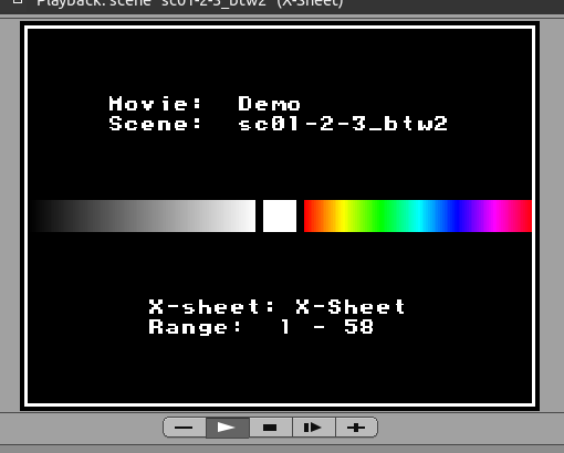
The Safety frames switch puts visible frames around the edges of the picture. The important contents, such as title texts usually must be inside these frames to avoid clipping by the television screen.
With the View: menu, it is possible to set different color modes for the viewing:
Color - full color mode,
Gray - grayscale black and white mode,
Red, Green, Blue - to check the individual color channels.
You can set the quality of viewing by the Visual quality: menu. It has options for three quality steps, but all of these are draft modes only. Occasionally, for a high quality but slowly rendered image, use the Final quality menu button on the player window.
Normal (Fast), Better, Best (Slower) - you can choose between better quality but slower, or worse quality with faster rendering.
Use the Stereoscopic: menu to select a stereo 3D view. If you have a stereo capable display, you can use its interlaced stereo format, or you can select filter modes for anaglyph color glasses, like the red-cyan type. There are also modes for crossed eye viewing techniques.
Off - stereoscopic view disabled, this is the default,
Anaglyph Red/Cyan, Anaglyph Amber/Blue, ... - color filter glasses for anaglyph 3D,
Interlaced (horizontal), Interlaced (vertical) ... - supporting modes for stereoscopic display hardware,
Right and left, Left and right (SBS) ... - modes based on crossing the viewer's eye axes.
You can combine the scenes in any order within the program. Depending on the speed and memory capacity of the computer, you can view the film in full, or in parts. For assembling the film click Playlist button on the main window.
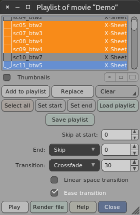
In the new window you can see a list to describe the projection order of the scenes. To add scenes into the list, open the scenes window by clicking on the Scenes... button of the main window and select the scenes you want to insert. You can select several scenes at once. In the latter case, the program will insert these scenes by the same order as you can see them in the scenes window. Then go back to the Playlist window and click on the Add to playlist button. The selected scenes will be inserted into the selected position of the list.
You can overwrite one of the list elements by another element with the Replace button. For example you can replace the layout or rough animation scene with the inbetweened version when it is finished. You can delete the selected list elements by using the Clear button. The button also have an option Clear all in its menu to clear the entire list at once, and an option Deselect all, to deselect the selected range on the list.
The Select all button selects all elements on the list at once.
In the course of cutting a film, frames can be omitted from the beginning and end of the scenes. This will not be deleted from the scenes, only it will not be visible during the projection. You can give the number of frames to omit at the starting of the selected scene by Skip at start: field. For the end of the scene use End: field, where the number of dropped frames can be defined in three ways:
Skip - number of frames left out of the end of the scene,
On frame - the serial number of the final frame of the scene,
Length - the length of the scene.
You can set the transition between the selected scene and the next scene in the Transition: field, where you can set the type of the transition and its length. In the course of transition the two scenes overlap over time.
With the Linear space transition option you can use linear color space for the transitions and with Ease transition, the transition will have a soft start and end.
To save the list of scenes, use the Save playlist button. This saves only the list arrangement of the scenes and not the scenes themselves. The list can be reloaded by the Load playlist button.
You have to select the range you want to play or render. The selected part is displayed in the list with a different color. You can set the first scene of the range with the Set start button and the last with the Set end button. You can select this range also if you move the mouse over the list while holding down its button.
To start playing the selected scenes, click on Play button, to get the playback window.
If you want to render the concatenated scenes to some external file format, open the Playlist window, then select the scenes on the list and click on the Render file button. Then you get a file saver window, where you can set the parameters of the file to save, like an image sequence. The program renders the scenes as a concatenated, single image sequence, along with the cuts and transitions set in the playlist window.
The program remembers the size of the windows, their location on the sceen and even their inner subdivisions, just like the parameters of the list editing, the playing or the digitizing.
When the size of a window or its internal subdivisions are not correct, it could be a drawback in the usage of the program. If a control, like a slider has not enough space, that control could disappear. After the first start some windows might have wrong dimensions, too big or too small. Then just resize the window, the program will remember the new size afterwards.
You can change the appearance of the program, the language and other settings on the About window of the user interface.
More detailed configuration is possible when editing the text file
named “gcnf” in the “var”
subdirectory.
The user interface of the program highly depends on the textual informations. The labels of the buttons and the error messages are built into the program in English (US). The user interface can use another languages and the English mode is expandable too.
The language files are located in the “var/langs”
directory. The namings of these files have a common scheme. The first
4 letters of the name are defining the language, the second 4 letters
are the function of the file, and at the end there is a “.lng”
extension.
The base files are containing the essential texts for the program, the English (US) version of this file is a built-in part of the program. Short descriptions for the elements of the user interface are in the help set, and the docs files are containing the translated versions of the manual for the different languages (the latter is called book for the previous commercial version).
You can learn more about these files in the next Chapter 10.1.1.
The most easiest way to set the language is to select from its menu in
the About window. But you can also give one or more languages
in the “var/gcnf” file. This
will be active when the Default (gcnf) option is selected in
the menu. Use this format:
language <name of the language>
The name of the language is the name in the given language or in English. For examlple, the Hungarian language can be selected with the word magyar, or the french with french. You can add multiple languages, in this case if a sentence is missing from one language, it will be substituted from another language. The English (US) language is there by default. Because growing of the program increasing the amount of sentences as well, if you are using an older translation for a newer program, you will see the English translation instead of the missing sentences. The manual reader in the program inserts an error message into the text if the contents of a chapter is not matching with the current functionality.
It is recommended to upgrade the language files together with the program, by letting the program to install the *update files.
This chapter can help you to translate the program's user interface, or
to customize the existing language translations. The language files
for the software are located in the “var/langs”
directory. The first 4 letters in the language file names are defining
the language, the second 4 letters are the function of the file, and
at the end there is a “.lng” extension.
For example, the “hungbase.lng” is the main ( base
) part of the Hungarian ( hung ) translation.
Currently the recognized languages contain the official languages of the European Union, and some other potentially (also from animation perspective) important languages too. Please note, that Firka currently can handle error free only left-to-right writing modes that do not require special (language specific) treatment. The right-to-left writing languages are specially badly supported under Linux.
These are the code names for the languages:
bulg - Bulgarian (no translation),
chna - Chinese (no translation),
croa - Croatian (no translation),
czec - Czech (no translation),
dans - Danish (no translation),
dutc - Dutch (experimental, corrections are
needed),
engk - UK English (no translation),
engl - US English (fully translated, THIS
IS THE DEFAULT),
esto - Estonian (no translation),
finn - Finnish (no translation),
fran - French (experimental, corrections
are needed),
germ - German (experimental, corrections
are needed),
gree - Greek (no translation),
hung - Hungarian (fully translated),
indo - Indonesian (no translation),
irsh - Irish (no translation),
ital - Italian (no translation),
japa - Japanese (experimental, corrections
are needed),
kore - Korean (no translation),
latv - Latvian (no translation),
lith - Lithuanian (no translation),
mala - Malay (no translation),
malt - Maltese (no translation),
mong - Mongolian (no translation),
norw - Norwegian (no translation),
pols - Polish (no translation),
porb - Brasilian Portuguese (no translation),
port - Portuguese (no translation),
romn - Romanian (no translation),
russ - Russian (no translation),
serb - Serbian (no translation),
slve - Slovene (no translation),
slvk - Slovak (no translation),
span - Spanish (no translation),
spaa - American Spanish (experimental,
corrections are needed),
swed - Swedish (no translation),
turk - Turkish (no translation),
ukra - Ukrainian (no translation),
viet - Vietnamese (no translation).
It is possible to translate to other languages, but those will appear in the menu only with their four character codes from the filename. Language file types, sorted by the function code:
base - the texts for the user interface, for
example the labels of buttons and menus, and the error messages are
included here. Its English (US) version is a built-in part of the
program, but, to support language translations, its copy is available
in the languages folder as well, under the name “englbase.lng”
. The English (US) translation acts as default, if a text is
missing from a translation, the English (US) version appears instead.
help - contains tooltips texts for the user
interface elements, and also the short descriptions for windows, for
use when the manual file (“docs”) is not available. The absence of
this file does not affect the operation of the program, if a
translation missing, the English (US) version appears, or just nothing
when the English (US) version is missing too.
docs - the user's manual. The HTML manual on the
website is generated from this (it contains the pictures too), also
pressing the Help button in some windows of the program
invokes a text-only version of the manual, readable within the
program.
The “xxxxbase.lng” and “xxxxhelp.lng”
files in the languages folder can be used as templates to
begin new language translations. These do not appear on the list of
selectable languages. They contain the English language texts, which
are also embedded as remarks next to each text.
Firka is still able to run if the languages folder is empty or missing, because the English (US) base texts are encoded into the program code.
Encoding of the “base” and “help” language files:
To understand this part, it is useful to open a language file. You can
use a text editor which is able to edit UTF8 encoded simple text
files. The format of the “base” and “help” files are
identical. Corresponding to the C language, you can enter remarks
between /* and */ boundaries (even in
multiple lines). These are not part of the encoded data. The format of
the translated texts is the following:
symbolic_name = "translation"
The translated texts are encoded with UTF8 code, additionally, the following escape sequences are usable:
\n \r \t \b \f \" \\
- control characters as in the C language, quotation marks and backslash,
\xx
- three character escape sequences, mostly for accented and special
characters. The usable codes can be retrieved by looking at the files
in the “var/charmaps” directory. But if it is
easier, you can use the UTF8 encoding for the same characters.
'x :x ;x `x ^x ~x
- shortened encoding specially for accented characters, to replace the
same \'x or \:x etc. sequences. In these
sequences, the first charater represents the accent, and the second
character is the original ASCII letter, without the accent. Because
this affects the entering of ' : ; ` ^ ~ characters, if
these are standing alone in the text, an additional space character
must be entered after them. This extra space does not appear in the
text. But if the character stands right before the end quote of the
text, you can leave this space out.
For example:
"Példa:" = "P\'elda: " = "P'elda:" .
If a text is too long to fit in one line, it can be entered to multiple
lines, but there must be quotation marks in all lines around the text.
Only the parts between the quotation marks belong to the text. If
there is a comma ( , ) right after the end quote of a
line, a line feed character is inserted to the text. There are a few
multiple line texts in the language files, that are using this
encoding.
From command line, you can use the
firka -s xxxxyyyy.lng
command to export the current state of any “base” or “help”
language files. The xxxxyyyy.lng means a valid language
file name here, for example hunghelp.lng . The symbols in
the exported file are in fixed order, the missing entries are replaced
with the English (US) translation. This way, after changing to a new
version, by comparing the files, it is easy to find the missing,
additionally inserted or changed symbols and translated texts. If you
use -S (uppercase) for the command option, the English
texts will be added as remarks to the translations.
The “docs” is also using the same text encoding as above, but the entire file is one continuous text. In the manual, special codes referring to the chapters, the navigation in the text, the symbols of the language translations and keyboard shortcuts. Additionally, exclusively for the HTML version, there are formattings, HTML codes and references to images. Because of these, modifying or translating the manual is a complex task, which requires extra care.
Some encoding rules for the “docs”:
- 3 spaces in the beginning of the line: retracted paragraph,
- 4 or more spaces in the beginning of the line: central text identation,
>chapter_name 1.0 Chapter name - the start of the
individual chapters,
<text> - text in bold style,
<-chapter_name Label> - link to a chapter,
<%chapter_name - subtitution of the chapter number,
>-symbol - subtitution of the user interface label,
>@symbol - subtitution of the keyboard shortcut.
<@text> - only viewed in the HTML version, raw text
encoded in HTML format.
Regarding to translations, for possible further help or cooperation, please contact the Author.
When using the external cache, in the edited scene the program selects pictures larger than the limit value, and temporarily puts them to files on the harddisk and keeps only a reduced resolution copy in the memory.
Besides you can configure this cache in the About
window, you can set it also in the the “gcnf”
file, located in the “var” directory. Enter
the following row into it:
cache <number of pixels> <size limit> <path>
After the cache keyword enter the maximal number of
pixels for a picture, then the highest size of the compressed image in
the memory (use the K and M suffixes for
kilobytes and megabytes), and finally the access path of your
temporary storage directory.
For example if on Windows you made a directory on the C:\
local harddisk with the access path firka\temp ,
and you want to limit the resolution to cca. 600x400 pixels and the
memory usage to 20 kilobytes per picture, then the right setting is
this:
cache 300K 20K C:\firka\temp
For those users, who have disabled “administration”
in the “tilt” file, the only
way to use the cache is this “gcnf” configuration.
The “gcnf” file is located in the “var”
directory, and the program creates it during its first
running. The file is in text format and you can edit it with any text
editor. Save it into ASCII text format. You can use the existing
“gcnf” as a template to add your own settings. The
user interface themes in the “*-themes” directories
are using this format too.
The text can contain full row comments, these rows are beginning with
the # mark. In the original “gcnf”
file some settings are commented out by a # at the start of
the row. You can make these active by deleting the # character.
The settings are in a [NAME] [VALUE] format, one setting is one row. The name consist of one or more tags, separated by the dot character. The tags can be in any order within the name. This is an example:
sheet.select.style raised
One group of tags to select the type of the window:
window
normal windows (default),
dialog
dialog windows, error messages,
Tags to select the functional elements of the interface :
canvas
the background of the window (default),
label
text labels,
button
command buttons,
control
“checkmark” switches,
scrollbar
scrollbars, sliders,
input
text input fields,
list
lists,
display
projecting surfaces, displays,
header
the headline of the exposure sheet,
sheet
the levels of the exposure sheet,
cursor
cursor in lists (in the exposure list as well),
sizer
internal subdivision sizers in the window,
help
the windows of help and their text messages.
There are subtypes for the button type, for
different kinds of buttons, like:
button_cancel
cancel the operation, close the window,
button_danger
cautious action, for irreversible operations,
button_exit
close the window,
button_file
file operations,
button_help
help requests.
...and so on.
At the end of the names it is possible to define another states:
button_on
activated state, switched on,
button_inactive
disabled, out of order state,
button_on_inactive
disabled in an activated state.
The pushed or released state:
select
pushed, selected control element.
Drawing properties:
frame
thickness of the framings, it's value can be:
- thickness in pixels, or
- thin line: thin,
- thick line: fat,
- no frame: none
style
style of the framings:
- simple: solid,
- raised embossed: raised,
- sunken embosed: sunken,
- combined: raisedsunken, sunkenraised,
complexity
the complexity of the drawing, it can be:
- very simple: poor,
- simple: normal,
- complicated: fancy,
- more complicated: extra,
font
the name, size and other parameters of the text font.
The colors of the element:
background
background (default),
foreground
things over the background,
text
texts,
highlight
highlighted parts,
leftedge
3D border on the left side,
topedge
3D border on the top side,
rightedge
3D border on the right side,
bottomedge
3D border on the bottom side,
block
in the exposure sheet the background of the selected block,
blocktext
in the exposure sheet the text of the selected block,
first
in the exposure sheet the first frame of a motion step,
If a name does not select a tag from a component group, it will affect the default component. An undefined value inherits the matching defined value. The settings described so far are usable also in the GUI theme files, but the settings below are usable only in the gcnf file.
Other settings:
language
Selects the language translation. The default is the English
(US English). The location for the language translations is the “var/langs”
directory. The currently available names are, for example:
- English (US): english
- Hungarian: magyar, hungarian,
- French: french, francais,
- German: deutsch, german.
An unknown name will be used as the first 4 letters of the language files.
path
Redirecting the common database for multiple programs, for example when
using a network. From the “var” directory only
directories will be redirected, not the files like “gcnf”
file. Enter a path to the directory where the “var”
and the “movies” directories located.
Normally this is the folder where you can find the Firka
executable as well.
workscreen
The properties of the picture when played in a window. The available options are highly dependent on the operating system and the hardware. You can find more details in the “gcnf” chapter that specific to your operating system.
playscreen
Playing properties for full screen viewing.
audio
Properties of the audio output.
printer
The geometrical properties of printing.
capture
Setting up the picture digitizer devices.
reminder
Setting the default time value in minutes for the save reminder function.
cache
Sometimes handling the high resolution pictures in the scenes can be problematic. The processing slows down, the usage of the program becomes uncomfortable. With the cache function you can reduce the load on the computer by keeping the high resolution pictures on a storage disk in temporary files, while substituting these pictures with low resolution copies in the memory. You can find more about the cache in Chapter 10.2.
The system-dependent parameters that can be used in the gcnf file under Windows are the followings:
Fonts can be given with the font name, and with the height, concatenated with style. The available styles:
- medium thick: m,
- bold: b,
- extra bold: k,
- italic: i or o,
- underline: u.
Multiple styles can be used together. This is an example:
font Arial 12bi
Colors can be given in hexadecimal with in BBGGRR order, or you can use the colors of the Windows user interface:
activeborder
activecaption
appworkspace
background
btnface
btnhighlight
btnshadow
btntext
captiontext
graytext
highlighttext
highlight
inactiveborder
inactivecaptiontext
inactivecaption
menutext
menu
scrollbar
windowframe
windowtext
window
As a system independent solution, you can use the #RRGGBB format with hexadecimal numbers.
These are the examples:
control.highlight 0000FF
sheet.blocktext.text btnface
list.select.text #001030
Parameters of the playing (the parameter value must be right after the
name without spaces, i.e. percent100 ):
workscreen
These settings can be used on all operating systems:
- user interface scaling: guiscale percent ,
- mouse wheel zoom in the old Firka style: oldwheel,
- flip mouse wheel zoom directions: flipzoom.
For problematic cases:
- picture generation through DIB: dib,
- 16 bits/pixel RGB555 (32768 color) mode: 555,
- 16 bits/pixel RGB565 (65536 color) mode: 565,
- slower compositing: slow,
- picture aspect ratio distortion: distortion percent
,
- play speed correction: speed percent .
playscreen
These are the settings for fullscreen playing:
- picture size: percent percent ,
- picture aspect ratio: shape x:y ,
- picture horizontal offset: left percent ,
- picture vertical offset: top percent ,
- picture aspect ratio distortion: distortion percent
.
If the word after playscreen is not one of the
above, the program will treat it as a name for the fullscreen output
device. Currently these are the names for Windows:
- view on the workscreen (default): default.
Sound output settings:
audio
By default the program is using a 22050 Hz, 16 bits stereo sound. If it was not successful, it tries another (8 bits, mono) modes too. Use these settings to change the defaults or to disable audio:
- disable audio: off,
- mono sound: mono,
- stereo sound: stereo,
- 8 bits mode: 8,
- 16 bits mode: 16,
- 44100 Hz sound: hifi,
- audio speed correction: speed percent .
Printer settings:
printer
Because when printing the pictures the geometrical accuracy could be important, it is possible to set these for the printer too:
- picture aspect ratio distortion: distortion percent
,
- allocating memory with the old “GlobalAlloc()” call: globalalloc.
Redirecting the path:
path
Use the standard path format of Windows, the newer Window systems are able to use both the slash and the backslash separator characters in the names. Network names are also accepted. It is recommended to give an absolute path.
The system-dependent parameters that can be used in the gcnf file under Linux are the followings:
The font can be given in the standard format of X-Window, for example:
font -adobe-helvetica-medium-r-*-*-10-*-*-*-*-*-*-*
Firka supports the font handling based on the languages. It can change
the font code page based on the selected language. To use it, add a
wildchar (*) character to the end of the name after the -iso8859
part, for example:
font -adobe-helvetica-medium-r-*-*-10-*-*-*-*-*-iso8859-*
On newer Linux systems there is another font system, this works with
UTF8 (Unicode) characters. This function is enabled by default, but
otherwise it can be activated in the workscreen
settings with the utf8 option (see below). The old
font names are still usable, the program extract the information from
them (family, slant, size etc.). Additionally, a simplified format is
usable, fonts can be given with the font name, and with the height,
concatenated with style. The available styles :
- medium thick: m,
- bold: b,
- black: k,
- extra black: x,
- italic: i,
- oblique: o.
Multiple styles can be used together. This is an example:
font Arial 12bi
Colors can be given by the standard color names and numeric formats of the X-Window. You can use the #RRGGBB format with hexadecimal numbers. The usable color names can be listed with the showrgb shell command.
These are the examples:
select.background Gray70
list.select.text #001030
Parameters of the playing (the parameter value must be right after the
name without spaces, i.e. percent100 ):
workscreen
These settings can be used on all operating systems:
- user interface scaling: guiscale percent ,
- mouse wheel zoom in the old Firka style: oldwheel,
- flip mouse wheel zoom directions: flipzoom.
Usable settings for 256 and less colors (indexed palette) screen modes:
- number of palette colors: palette number ,
- enabling dither pattern: dither,
- RGB palette instead of YUV: rgb,
- grayscale palette: gray.
Use these settings only for problematic cases:
- screen geometry: xyimage, zimage,
- in xyimage the LSB bitplane is the first: lowtohigh,
- disable XShm memory sharing: noshared,
- if the drawing of the GUI is too slow (disable XRender): noxrender,
- slower compositing: slow,
- picture aspect ratio distortion: distortion percent
,
- play speed correction: speed percent .
Activating UTF8 (Unicode) character set support:
- UTF8 characters: utf8 or utf8="family"
For the utf8 mode you need the Xft
extension of X-Window. Without this, or if the scalable fonts are not
suitable, some characters will not appear or the font style could be
different from the required. This mode has an effect on the handling
of the file names, characters outside of the 7 bits ASCII character
set are treated like UTF-8 encodings. On the newer Linux systems this
is the default, so on these systems it is useful to use this mode, to
process the file names correctly. Because the old font settings are
not always suitable to Xft, after the utf8 option
you can give a font family name and the system
will use it to replace the old (found in old user interface themes)
font parameters.
playscreen
These are the settings for fullscreen playing:
- picture size: percent percent ,
- picture aspect ratio: shape x:y ,
- picture horizontal offset: left percent ,
- picture vertical offset: top percent .
- picture aspect ratio distortion: distortion percent
,
- terminal switching for playing: vt= terminal number
.
If the word after playscreen is not one of the
above, the program will treat it as a name for the fullscreen output
device. Currently these are the names for Linux:
- view on workscreen (default): default,
- view on a specific X-Window display: xdpy=display-name
.
Sound output settings:
audio
By default the program first tries to start the Jack sound server, then the PulseAudio sound server. If none of them were successful, then it tries to set a 22050 Hz, 16 bits stereo sound on the OSS sound system. If this also failed, it tries other modes too. Use these settings to change the defaults or to disable audio:
- disable audio: off,
- mono sound: mono,
- stereo sound: stereo,
- 8 bits mode: 8,
- 16 bits mode: 16,
- 44100 Hz sound: hifi,
- audio speed correction: speed percent ,
- disable jack sound server: nojack.
- disable pulseaudio sound server: nopulse.
Printer settings:
printer
Because when printing the pictures the geometrical accuracy could be important, it is possible to set this for the printer too:
- picture aspect ratio distortion: distortion percent
.
Redirecting the path:
path
Use the standard path format of Linux. You can use paths begining with the tilde character (the user's “home” folder) too. It is recommended to give an absolute path.
The system-dependent parameters that can be used in the gcnf file under OSX are the followings:
Fonts can be given with the font name, and with the height, concatenated with style. The available styles :
- bold: b,
- italic: i,
- oblique: o
Multiple styles can be used together. This is an example:
font Arial 12bi
Colors can be given in the #RRGGBB hexadecimal format, or with the following names:
activeborder
activecaption
appworkspace
background
btnface
btnhighlight
btnshadow
btntext
captiontext
graytext
highlighttext
highlight
inactiveborder
inactivecaptiontext
inactivecaption
menutext
menu
scrollbar
windowframe
windowtext
window
These are the examples:
select.background window
list.select.text #001030
Parameters of the playing (the parameter value must be right after the
name without spaces, i.e. percent100 ):
workscreen
These settings can be used on all operating systems:
- user interface scaling: guiscale percent ,
- mouse wheel zoom in the old Firka style: oldwheel,
- flip mouse wheel zoom directions: flipzoom.
Use these settings only for problematic cases:
- slower compositing: slow,
- picture aspect ratio distortion: distortion percent
,
- play speed correction: speed percent ,
- UTF8 characters: utf8.
playscreen
These are the settings for fullscreen playing:
- picture size: percent percent ,
- picture aspect ratio: shape x:y ,
- picture horizontal offset: left percent ,
- picture vertical offset: top percent ,
- picture aspect ratio distortion: distortion percent
.
Sound output settings:
audio
Under OSX the program is using system provided sound settings. The usable sound parameters:
- disable audio: off,
- audio speed correction: speed percent .
Printer settings:
printer
Because when printing the pictures the geometrical accuracy could be important, it is possible to set this for the printer too:
- picture aspect ratio distortion: distortion percent
.
Redirecting the path:
path
Use the standard path format of OSX. You can use paths begining with the tilde character (the user's “home” folder) too. It is recommended to give an absolute path.
When multiple users have access to the Firka program, maybe you set
limited access rights to the program's functions for some users. For
example they can play the scenes, but modifications are forbidden.
With the “tilt” file you can manage these
restrictions. This file is located in the “var”
directory, just like the gcnf file, but the
program does not create this file by itself.
You can enter the following keywords into the “tilt”
file, one row should contain one keyword:
write_movie
disables movie creation, delete and modify,
write_scene
disables scene creation, delete and modify,
write_xsheet
disables save for the edited scenes,
write_objects
disables save of objects (pictures, sounds etc.) into external files,
write_to_file
disables save of scenes into external files and generally all saves are disabled,
read_from_file
disables load of scenes from external files and generally all loads are disabled,
print
disables printing,
digitize_picture
disables picture digitizing,
write_picture
disables picture editing (digitizing and painting),
write_sound
disables sound editing,
edit_movements
disables editing of the movers,
play_scene
disables the player,
play_sequence
disables manage of concatenated scenes (Playlist window),
administration
disables modification of settings on the About window.
There are special keywords:
operator
linetest operator combination, modifying movies are disabled,
painter
painter user, the colors, the movers, the movie scene and exposure sheet operations, file operations are restricted.
line-test, painting, renderer
the nature of the workplace.
logging <username>
logging of the events happened to the scenes. The username is the
symbolic name of the machine or the user to use in the log. If you not
give it, the program will use the user's login name. The log
will be located in an encoded format in the “var/admin”
directory. Its name is lgop (lgnp..) , according
to the allocated serial ID of the running program instance.
gcnf.os
the program reads its gcnf configuration from a file named by the used
operating system. For example, “gcnf.w” (Windows) or
“gcnf.l” (Linux). In a network of mixed operating
systems - with different gcnf requirements - this permits the use of a
common “var” directory.
gcnf.user
the program reads its gcnf configuration from a file named composed
using the *user settings (see below). With this you can
assign gcnf settings for different machines individually in the same
“var” directory. The last part of the name will be
the letter of the operating in this case too!
Easily possible that a user starts the program on the same machine in
multiple instances. To avoid this, in the “tilt”
file you can specify the allocation of a separate key before the
program starting. The key in this case is a number between 0 and 255
and only one program instance can allocate it at once. You can give it
this way:
*number
You can put multiple keys into the “tilt” file, the
program will allocate the first free from them. If all of the keys are
taken, the program won't start.
A useful option in the “tilt” file is this:
*user
*host
*user.host
In this case the name of the configuration files in the “var”
directory is extended with the login name of the user (user)
and the name of the computer running the program (host). With these it
is possible to keep all of the data of Firka in the same single
folder, located on a server of a bigger network. In the same time this
option allocates a key by the name so a user or a computer can run
only one instance of the program at the same time. If one of the
gcnf.os or gcnf.user options is also
specified, the last part of the name will be the letter of the
operating system:
Windows: .w,
Linux: .l,
OSX: .m.
From the 3.0 version the access to the movies can be managed using the login name of the user. In this case you have to specify the administrator users. These users have access to all of the movies, they can change the access rights as well. For these keeper users use this
owner user1 ...
option format. You can specify multiple user names, separates by spaces.
If the owner option is in the “tilt”
file then it is possible to set the access rights of the users
for each movies separately. You can read more detailed information
about this solution in Chapter 4.2.1.
It is possible to install a system for multiple workstations to connect to the same database over a local network.
To achieve this first install the program to the computer where you want to keep the database of scenes. This could be a workstation, but in larger networks it's better to use a separate server machine.
If you have different operating systems on the workstations, copy the needed variations of the executable file into the program's folder.
In the “tilt” file you can
enter a row in “*user.host” format, then each users
on each computer will use separate settings about the position of the
windows or about the preferred language. In networks with mixed
operating systems it is useful to set the “*gcnf_os”
option, and then the name of the operating system will be added to
the name of the “gcnf”
configuration file (for example, “gcnf.w” ). This
is useful because different operating systems need different
configurations. If this is the case, you have to make the copies of
the “gcnf” file manually.
If these configuration options are not enough, for example because some users need unique access, you have to install the program on the workstations one-by-one. On Linux or OSX you can make symbolic links to redirect the executables into a shared place on the network. This helps to make upgrading the program easier, you have to replace it only once in the system.
On all of the machines, install Firka and run once to create its
directory structure. After that exit the program and enter the
following row into the “gcnf” file of the “var”
directory:
path <Path to the shared folder>
This redirects the database of the scenes (the “movies”
directory) and some contents of the “var”
directory too, but not the location dependent data (contents of the
“gcnf” directory, the “mscf”
character set or the saved settings from the last running). This
solution ensures the shared access of data while the machines can be
independently configured.
Also a possible solution to create multiple startup folders on the same computer for each user.
It is possible to restrict the functions of the program by the workstations or by individual users. In this case it is essential that the starting folders are read-only, otherwise the users may change their access rights.
When connecting the machines to a network a source of problems can be if the network filesystem is not able to handle the locking of files. A lock allows the program to protect a file from access by other programs. Firka works correctly only if this mechanism is right.
If you want to upgrade your already installed program to a newer
version, download the installer packet of the new program and write
over the executable file in the folder of the existing program, and
also copy there the “*update” file too, for the
language and other updated data.
Change these files on the different operating systems:
Windows:
“firka.exe” and “wupdate” ,
Linux:
“firka” and “lupdate” ,
OSX:
“firka” and “mupdate” .
If you are using the program on multiple operating systems, you have to start the program on each operating systems to install the updates.
USE THE CONTENTS IN THIS CHAPTER ONLY IN THE LAST RESORT, BECAUSE AN INACCURATE EXECUTION CAN CAUSE LOSS OF IMPORTANT SCENE DATA. PREFERABLY DO NOT REINSTALL THE PROGRAM, OR AT LEAST DO IT BY COPYING THE ENTIRE FOLDER OF THE PROGRAM!
It is possible that you must reinstall the program - or the entire operating system - in case of a hardware failure or when an operating system crash occured. The current free version is much less sensitive to this than the older commercial version with all its built-in protections, but still be careful to avoid any data loss.
The best way of reinstalling if you entirely copy all the old contents of the program's folder into a new place. Then you can continue working in the new folder.
Sometimes, an accidental delete or a faulty harddisk happens and the old database is not or only partially available. Then you can make the restoration by using previously saved external scene files. These must be in the FFS format (the own scene file format of Firka). By all means don't write over the remained scenes in the internal database, instead create new scenes and delete the old version only when ensured that the restored version is right - or don't delete at all.
Because of such cases, from time to time it can be useful to archive the scenes of the internal database in the movie being produced. Preferably do this to an external, removable data storage (harddisk), by using Firka FFS file format. Keep the archive in a safe place away from the computer.
Mouse buttons:
The control elements usually can be activated with any mouse button, but in some cases there are special functions connected to mouse buttons:
Right mouse button
- show the menu of the control element,
Ctrl+Left mouse button, Right mouse button, Ctrl+Middle mouse button
- zoom in and out the displayed content by dragging up or down,
Shift+Left mouse button, Ctrl+Left mouse button, Right mouse button, Middle mouse button
- move the displayed content by dragging.
Mouse wheel:
Wheel Up, Wheel Down
- zoom in and out,
Shift+Up, Wheel Down, Ctrl+Wheel Down, Shift+Down, Wheel Up, Ctrl+Wheel Up
- vertical scroll,
Shift+Left, Shift+Wheel Down, Shift+Right, Shift+Wheel Up
- horizontal scroll.
Generally used keyboard commands in the windows:
Return/Enter
- Close, OK., Continue buttons, confirm the operation,
Esc
- Cancel button, exit, abort the operation,
U, Esc, Ctrl+U, Ctrl+Z
- Undo, revoke the operation,
Ctrl+C
- Copy, remember the selected content,
Ctrl+X
- Cut, remember and delete the selected content,
Ctrl+V, Ctrl+Y
- Paste, insert the previously remembered content,
Ctrl+A
- Select all, select the entire content,
C
- clear the setting or content,
I
- turn the setting or content to its inverse,
Backspace, Delete
- Delete, remove data,
F11
- full window edit mode.
Usable in the main window:
M
- open the Movies window,
S
- open the Scenes... window,
E
- open the Editor window,
P
- open the Playlist window,
A
- open the About window.
Usable in the file loader and saver windows:
C
- clear the selection on the list,
I
- invert the selection, which is not selected, will be selected and vice versa.
Ctrl+Backspace
- step up one level in the directory hierarchy, to the parent folder,
D
- when listing the “movies” directory, deselecting
the safety copies of scenes,
M, Ctrl+M
- when listing the “movies” directory, deselecting
the scenes which has no small mark,
Operations:
Ctrl+N
- new empty scene,
F11
- open the Play window,
F2
- open the Record window,
F9
- open the Level properties window of the cursor's level,
Ctrl+S
- save (overwrite) scene,
Shift+Ctrl+S
- save scene under a new name,
Shift+Ctrl+O
- load another scene,
Ctrl+O
- load item,
Ctrl+P, Shift+Ctrl+P
- print the exposure sheet,
Ctrl+P
- print item,
Shift+F6
- open the Override playback format window.
Working modes and parameters:
Tab, Ctrl+I, Insert
- next insert mode (Overwrite, Insert ...),
Ctrl+Tab, Ctrl+Insert
- change the insert mode to overwrite,
F8
- increase value of the Step: field,
F7
- decrease value of the Step: field,
Ctrl+Space
- switch on or off the automatic name increment, to enter a name series to the X-sheet,
F3
- highlighting the row of the cursor,
Moving in the X-sheet:
Left, Up, Right, Down
- move the X-sheet cursor,
PgDn
- jump forwards to the begining of the next motion step,
PgUp
- jump backwards to the end of the previous motion step,
Home, Shift+Home, End, Shift+End
- jump to the begining and end of the level content,
Entering to the X-sheet:
Ctrl+E
- move down the end of the motion step before the cursor, to the cursor,
Ctrl+G
- move up the begining of the motion step after the cursor, to the cursor,
Plus (+)
- insert one frame at the cursor, or if a block selected, at all motion steps of the block,
Minus (-)
- delete one frame at the cursor, or if a block selected, at all motion steps of the block,
Delete, Ctrl+D
- delete the frame at the cursor,
Ctrl+Return/Enter
- enter a remark,
Ctrl+V, Ctrl+Y
- insert the content of the last selected block into the cursor,
Esc, Ctrl+Z
- undo of X-sheet changes,
Ctrl+U
- undo of X-sheet changes but the cursor remains in place,
Picture properties in the X-sheet:
Ctrl+M
- switch mirroring of the picture,
Ctrl+J, F5
- displace the picture by one shifted peg position to the left,
Ctrl+K, F6
- displace the picture by one shifted peg position to the right.
Block operations:
Ctrl+B
- start and end block selection, clear block,
Ctrl+H
- set or relocate the begining of the block,
Ctrl+L
- set or relocate the end of the block,
Ctrl+W, Ctrl+A
- select the entire level content as block,
Ctrl+R
- reverse the order of the motion steps within the block,
Search:
Ctrl+F
- search for the content of the Item: field on the xsheet, after its cursor,
Shift+Ctrl+F
- jump the cursor of the right side list (items or effects) to the item located at the xsheet cursor.
Name entering, when the X-sheet cursor is a text input field:
Up, Down
- exit from the name entering, the name still will be written to the X-sheet,
Esc, Ctrl+F
- exit from the name entering, the X-sheet remains unchanged,
Return/Enter
- enter the name to the X-sheet on number of frames determined by the Step: field, the cursor moves down the same frames, and the entering continues.
Keys when the right side “items” list is the active:
Up, Down
- move on the items list,
Shift+Up, Shift+Down
- select a sequence of items on the items list,
Left, Right
- move on the X-sheet, in vertical direction,
Return/Enter
- enter the selected item into the X-sheet, or if a folder (subdirectory) is the selected one, step into that folder,
Space
- enter empty (blank) frame into the X-sheet,
Delete, Ctrl+D
- delete the frame above the cursor in the X-sheet,
Ctrl+Backspace
- if in a folder (subdirectory), step back to its parent folder.
Capture:
Return/Enter
- capture the current name,
Ctrl+Space
- in Exposure sheet mode mode, capture only, don't write it to the X-sheet,
Space, Ctrl+Return/Enter, Insert
- capture the next name, with increased serial number,
Delete
- read a picture in (in case of scanner or photo camera),
A, Divide (/)
- Accumulate button, multiple exposured picture,
Ctrl+A, Multiply (*)
- clear the multiple exposure,
L
- switch on the stereoscopic left eye,
R
- switch on the stereoscopic right eye,
Settings:
P
- capture a paper background for background removing,
Ctrl+P
- clear the paper background,
F4, F3
- brightness increase and decrease,
F6, F5
- contrast increase and decrease,
F8, F7
- increase and decrease the currently selected parameter on the list,
F12
- shadow display mode on and off.
Display settings:
Wheel Up, Wheel Down
- zoom in and out on the display,
Numpad-0
- show the entire picture and fill the display with it,
Numpad-1 ... Numpad-9
- set the zoom of the display,
Plus (+)
- increase the zoom (zoom in),
Minus (-)
- decrease the zoom (zoom out),
Shift+Left, Shift+Wheel Down
- scroll the display content to the left, if zoomed in,
Shift+Up, Ctrl+Wheel Down
- scroll the display content upwards, if zoomed in,
Shift+Right, Shift+Wheel Up
- scroll the display content to the right, if zoomed in,
Shift+Down, Ctrl+Wheel Up
- scroll the display content downwards, if zoomed in,
0
- switch Align pixels on, to align the picture to the pixel resolution.
Dialog windows:
K
- open the Chroma key window,
O
- open the Crop window,
T
- open the Timelapse window,
Backspace
- restart the timelapse counter.
Relocating the contents of Onion: , Over: , Under: overlays:
X
- set the rotation center for the overlay relocation, the overlays will rotate only around the selected point, without scaling,
H
- set the rotation center for the overlay relocation, the overlays will rotate and scale around the selected point,
Ctrl+Delete
- clear the rotation center.
Selecting the drawing mode:
M
- selection mode,
P
- color picker mode,
F
- flood fill mode,
O
- outline drawing mode,
L
- line drawing mode,
D
- freehand drawing mode,
F1 .. F6
- switch between the 1..6 tool state buttons,
F7, F8, F9, F10
- switch between the drawing color buttons.
Display settings:
Wheel Up, Wheel Down
- zoom in and out on the display,
Numpad-0
- show the entire picture and fill the display with it,
Numpad-1 ... Numpad-9
- set the zoom of the display,
Plus (+)
- increase the zoom (zoom in),
Minus (-)
- decrease the zoom (zoom out),
Shift+Left, Shift+Wheel Down
- scroll the display content to the left, if zoomed in,
Shift+Up, Ctrl+Wheel Down
- scroll the display content upwards, if zoomed in,
Shift+Right, Shift+Wheel Up
- scroll the display content to the right, if zoomed in,
Shift+Down, Ctrl+Wheel Up
- scroll the display content downwards, if zoomed in,
0
- switch Align pixels on, to align the picture to the pixel resolution.
Change selection mode:
N
- the Set new mode, the new selection will replace the old one,
A
- the Add mode, the new selection will be added to the old one,
S
- the Subtract mode, the new selection will erase from the old one,
K
- the Intersect mode, the common part will remain.
Operations with colors:
G
- pick a color from the picture,
T
- pick a color from the picture for the Target color: button,
Z
- switch between the current color and transparent color,
Y
- changes the color to full opaque while keeps the color hue,
Space, F12
- shadow display mode on and off.
In flood fill mode:
R
- swith on and off the Manual leak closure option
Ctrl+Shift+Left mouse button
- drawing of leak closing contours when Manual leak closure is off, starting a new fill otherwise.
For deforming operations:
X
- set the center for rotating,
H
- set the center for shearing,
Ctrl+Delete
- clear the center point.
The rotating or shearing center is also the starting point of cloning in the Clone drawing mode, and acts as a rotation center when relocating the Onion:, Over:, Under: overlays. For overlay relocation, around the center placed with X the overlay will rotate only, but with H it will rotate and scale.
When Exposure sheet mode is enabled:
Return/Enter
- create an item from the current picture with the current name and enter it into the exposure sheet from the cursor,
Ctrl+Return/Enter, Insert
- increase the numbering of the current name, create an item with it and enter it into the exposure sheet,
Backspace
- create an empty (transparent) picture for the current name. If it is an existing picture item, this means all of its picture sublayers will be deleted. Only if it is a new name that wasn't there before, it is also entered into the exposure sheet. If there is a selected area on the picture, this key command only clears the inside of the selection into transparent, the xsheet remains intact in this case,
Ctrl+Backspace
- increase the numeric part of the current name, create an empty (transparent) picture under the new name, and enter it into the exposure sheet.
Playing sound:
P, Return/Enter
- play the sound from the begining of the selection, or from the begining of the sound if nothing selelected,
Space, Insert
- stop the playing of the sound, or continue from the stop position,
B, Home, Shift+Home
- plays the first two seconds of the selection,
E, End, Shift+End
- plays the last two seconds of the selection.
Tab
- plays the 1/10 seconds around the current playing position and moves the playing position forwards. This can be useful when searching the exact position of some dialog part. During dialog breaking down, it plays the 1/10 second area around the breaking down position.
Display settings:
Wheel Up, Wheel Down
- zoom in and out on the display,
Numpad-0
- show the entire sound in its full length,
Numpad-1 ... Numpad-9
- set the zoom of the display,
Plus (+)
- increase the zoom (zoom in),
Minus (-)
- decrease the zoom (zoom out),
Shift+Left, Shift+Wheel Down
- scroll the display content to the left, if zoomed in,
Shift+Right, Shift+Wheel Up
- scroll the display content to the right, if zoomed in,
Shift+Up, Ctrl+Wheel Down
- increase the displayed amplitude of the sound waveform,
Shift+Down, Ctrl+Wheel Up
- decrease the displayed amplitude of the sound waveform.
During dialog breaking down:
Up
- move the input position backwards by one frame,
Down
- move the input position forwards by one frame,
Tab
- play the 1/10 second area around the input position,
Esc, Ctrl+F
- exit the input mode.
Stepping the frame position:
Right, Down
- step to the next frame,
Left, Up
- step to the previous frame,
PgDn
- jump to the next motion step of the current X-sheet level when Exposure sheet mode is on, otherwise step to the next frame,
PgUp
- jump to the previous motion step of the current X-sheet level when Exposure sheet mode is on, otherwise step to the previous frame.
Mover editing:
Ctrl+N
- if in the Independent mover overlay level, if it is empty, create a new mover,
Ctrl+Backspace
- if in the Independent mover overlay level, clear the motion path,
Ctrl+Return/Enter
- save the current mover with the name given in the Item: field,
Tab, Shift+PgDn
- step to the next element (segment or point) of the motion path,
Shift+PgUp
- step to the previous element (segment or point) of the motion path,
J
- step to the segment and percentage value of the current frame position on the motion path,
Ctrl+Tab
- step to the first element of the motion path (to the A
point),
E, Ctrl+E
- if an endpoint is selected, add a new segment to the start or end of the motion path,
S, Return/Enter
- split the selected segment by inserting a new point,
Insert
- split the selected segment by inserting a new, fixed key point (key points are marked with letters and can be referred from the X-sheet),
Delete
- delete the selected point or segment,
Shift+Left, Shift+Up, Shift+Right, Shift+Down
- move the selected element to a distance corresponding to one visible pixel,
O
- select the Independent mover overlay level on the left side list,
D
- select the Picture overlay: level on the left side list,
Working with switches:
F
- switch on or off the Fixed switch for the selected point,
K, Ctrl+K
- switch on or off the Key position switch for the selected point,
R
- switch on or off the Central view switch,
Z
- switch on or off the Level's 3D position switch, to adjust the spatial depth of the level.
Display settings:
Wheel Up, Wheel Down
- zoom in and out on the display,
Numpad-0, 0
- resets the display to its default, the entire projecting field will be visible at center position with medium scaling.
Numpad-1 ... Numpad-9
- set the zoom of the display,
Plus (+)
- increase the zoom (zoom in),
Minus (-)
- decrease the zoom (zoom out).
Other operations:
F5 .. F8
- select the input fields for numeric entering,
G, L, Ctrl+L
- select an X-sheet level from the picture,
C
- relocate the path point under the mouse pointer to the (0,0) position at the center, with a one unit long, zero-rotated size vector. This is the basic position, it has no effect on the moved content.
Backspace
- render picture in final quality,
Dialog windows:
N
- open the Add noise window,
P
- open the Pan & Scan window.
Positioning pegbars and level contents:
X, H
- set the fixed position, the center of rotation and scaling,
Ctrl+Delete
- clear the fixed position.
Controlling playback:
P
- start the playing from the first frame,
Space, Insert
- start or stop the playing at the current position,
Multiply (*)
- start the playing from the last start position,
Divide (/)
- start the playing from the last stop position.
Full screen playing:
F, Ctrl+F, F11
- switch on full screen mode,
F11
- start and stop playing on full screen,
Esc, Ctrl+F
- exit the full screen mode.
If playing is paused:
Home, Shift+Home
- jump to the first frame,
End, Shift+End
- jump to the last frame,
Right, Down, Plus (+), Wheel Up
- step one frame forwards,
Left, Up, Minus (-), Wheel Down
- step one frame backwards,
PgDn
- jump to the next motion step of the cursor's level,
PgUp
- jumo to the previous motion step of the cursor's level,
Shift+PgDn
- jump 10 frames forwards,
Shift+PgUp
- jump 10 frames backwards,
C
- switching on or off Play in cycle,
G, L, Ctrl+L, Left mouse button
- select a level from the picture with the mouse,
S
- open the Playback parameters: window.
Final quality rendering:
Backspace, Delete
- render a frame in final quality,
Return/Enter
- render the scene in final quality and start playing from the first frame,
Tab
- render the scene in final quality and start playing from the current position.
During its first start, the program creates a directory structure in the folder that contains the executable program. The program does not change any settings in the operating system, everything will be located in this same folder. If you want to delete or move the program, you have to delete or move this single folder.
The directory structure and the files created by the program are the following:
firka (Linux) or firka.exe (Windows) or Firka.app (OSX)
- the executable program
firkadbg (Linux, OSX) or firkadbg.txt (Windows)
- text file for logging events, it grows continuously and occasionally it should be deleted if it uses too much space. In case of an error, for example if there is no sound, it can help in detecting the cause of the problem.
movies
- Storage location for the scenes. The scenes are stored under special
code names that allow for platform-independent name management, for
example when data shared by multiple operating systems. The
subdirectories within the movies directory are the stored movies. In
these, names starting with “aaaaaaaa” contain the
catalog of scenes, their thumbnail images and other information. Files
ending with “v” in their extension are the
penultimate backups of the scenes. The scene files are saved in the
own FFS format of Firka, and can be loaded directly as external files
when necessary. About loading back these scenes, see also
Chapter 5.3.
var
- The location of the program's data storage. It contains:
admin
- subdirectory, contains the properties of the movies and other settings,
charmaps
- the location of the files containing the various character code sets
entity
- contains the data protection files of the program
gcnf text format configuration file
langs
- the location of the text files for the various language translations
lock
- subdirectory in network operation to manage shared access
mirror
- the copy of the “entity” subdirectory
mscf text format character set definition file, DEPRECATED
opers
- not used yet
scripts
- text format command script files, for example to make timelapse capture
shaders
- command script files for drawing
ucnf language and theme configuration
wcnf internal variables of the program (eg. window locations)
w-themes (Windows), l-themes (Linux) or m-themes (OSX)
- these directories contain user interface themes for the different systems. Due to the different capabilities of the operating systems, the themes are better managed separately. The structure of these text format files are similar to the gcnf file.
wupdate (Windows), lupdate (Linux) or mupdate (OSX)
- the update packages for different platforms. The downloaded installation package also contains such a file. It should be in the same folder with the program, then the program offers its installation when the program started. After the successful installation the program removes this file by renaming it to a backup name. When the program is first started, the contents of the update package are automatically installed without question.
The entity contains essential data for handling the scenes, which is stored for security reasons by mirror subdirectory too.
The mscf file and the contents of the charmaps directory contain the data needed to encode the characters of text fonts. The mscf overrides the automatically managed definitions in the charmaps directory, it may only be used in justifiable cases and not recommended.
Advanced users can create complex drawing scripts to enhance the capabilities of the Outline drawing mode.
The entries of color palettes can contain
%<letter>[<number>][<letter>[<number>]...]
style tags at the very beginning of their names. In shader scripts these are triggers for the (A..Z) attribute flags. Lot of shader operations are using these (and other) flags to differentiate pixels. This part of the name will not be visible on the palette items list.
In the name the optional number after the letter is useful for color translations when there are multiple possible results and the matching color is selected from these by its matching number value.
For example a palette contains these four entries:
(0) black color with name: “%A2 Black”
(1) blue color with name: “%A2B1 Blue”
(2) red color with name: “%A1 Red”
(3) yellow color with name: “%B2 Yellow”
When translating (replacing) colors containing attribute “A” to colors containing attribute “B”, the result could be “Blue” or “Yellow” because these have the “B” attribute. You can use the optional number to select from these.
In this case “Black” and “Blue” pixels will be translated to “Yellow”, but “Red” will be translated to Blue”, because for these the number after “A” is the same as the number after “B”. “Yellow” pixels cannot be translated as they have no “A” attribute. This way you can define multiple similar color translations with one simple rule.
The shader scripts are plain ASCII text files. The filename extension
is not important, but filenames ending with “.bak”
or “~” are ignored in the folder because these are
the usual backup copy names during an editing. The location for these
scripts is the shaders subdirectory in the var
directory of the program. If scripts are available, there will be a
Shader menu button at the Outline drawing mode of the
painting window.
The shader text file can contain commands, separated with the ;
character. Between these commands you can use C style /*
comments */ .
Arguments are command speciic and can be these ( [] means optional ) :
<layer> :
single digit number, 0..9. 1-8 is the image sublayer, 0 and 9 are auxilliary buffers.
<letter> :
A..Z and a..z , no differentiation on lower
and upper case. It means an attribute flag defined by the palette
color of the pixel.
<number> :
0..255 decimal numbers.
+<number> - add to the default value
-<number> - subtract from the default value
<key> :
<letter>[<number>][:<number>]
= - as a target:the color itself (remap:from the map,
filter:from the source)
# - the transparent color
* - any color, as a target:the color itself
@ - palette redirection to the active palette
The number after the : means direct palette redirection.
<minterm> :
[~]<letter>[[~]<letter>...]
Additionally to the alphabetical letters, you can use:
# - as the transparent color
: - neighbours are on the same palette
% - any RGBA coded pixel
* - any palette coded pixel
@ - marked by the outline command
It's a logical AND combination of attributes. The ~
before a letter means NOT, the condition will be true if the given
attribute is missing.
<condition> : (written between parentheses)
(<minterm>[|<minterm> ...])
Logical OR combination of minterms. Separate the minterms with the
| character. The minterms are processed from left to
right, until the first true result. If all minterms are false, the
value of the condition is also false.
Empty pair of parentheses means always true.
<translation> :
[<condition>]<key><(target)key>[,<translation>]
Translations connected with comma (,) are processed when the condition of the previous translation was true but the translation of the key was invalid. The condition part can be omitted or can be an empty pair of parentheses, these two means the same.
<mask> : (written between parentheses)
(<minterm>)
A single minterm to define an attribute flag mask to set
<%n> :
%<letter><number>
%<letter>=<name>[*<number>][/<number>][+<number>][-<number>][...]
%<name>
Numeric argument for quantity type values. The usable parameters are
depending on the command. The number can be 0..255
decimal value only, the +/- offset mode is not supported. With the
=<name> format you can access the sliders of the user interface,
in this case you can use multiplication (2..8) , division
(2..8) , addition and subtraction (-255..+255)
, in this order.
You can use these names to access the slider elements of the user interface:
ALPHA, RED, GREEN, BLUE, PENSIZE, PENMODE, PENSHAPE, PENPRESSURE
<;> : separator at the end of the command
List of commands:
blow [%afbsmdr] ;
%a - alpha weighting for the distance
%f - unfocus the map to get the alpha value
%b - enlarging (towards the empty regions)
%s - shrinking (towards the filled regions)
%m - maximal spike in the enlarging direction
%d - normal vector averaging (larger means stronger
averaging)
%r - random displacement
Translates the coordinates of the vector table in a direction.
 bumpmap <layer> [%rdmlac] [<mask>]
[<condition>] ;
%r - direction angle
%d - cleared length to scan length ratio
%m - minimal scan length (below this there is no change)
%l - length linearity
%a - alpha-ramp mode (0=off, 1=ratio based, 2=ramp)
%c - constant changed length
It scans the rows of the map and alternately clears the first-last half of the connected pixel series (scans). It can be used to create light-shadow effects. The mask determines the change on the attribute flags. If there is a condition given, the pixel only written if the condition is true.
Example: a map row (X= cleared pixel)
AAAAAAAAABBBBBBBBBBBCCCCCCCCCCCCCCDDEEEE
XXXXXAAAABBBBBXXXXXXXXXXXXXXCCCCCCDXXXEE
clear <layer>[<layer>...] [<condition>] ;
Clears the picture sublayer(s) to transparent. If a sublayer is missing, this does not create it.
 filter <(target)layer>[<source layer>]
<condition> <translation> [<translation>...] ;
Recolors by the contents of the target sublayer. It processes only the pixels where the condition is true in the source sublayer. The color of the pixel will be the first valid translation, with keeping the alpha value. If none of the translations are valid, the pixel value remains unchanged. If you dont want this, add a last unconditioned translation to the end of the row for the default color.
 mapclear [<mask>] [ condition>]
[<translation>...] ;
Sets the attribute flags of the pixels in the map to the mask. If condition given, only changes those pixels. If translation given, it changes the color information of the pixels. If there is no translation, or it is invalid for the pixel, the attribute flag bits are cleared. The condition and translation are using the current content of the map.
 mapedges <layer>[<layer>...] [%asxy]
[<condition>] ;
%a - overwrite the alpha component with the value. 0=
dont change.
%s - swap the two adjacent pixels in the map 0= dont
swap.
%l - for RGBA colors, put the 1=lighter or 2=darker to
the map. 0= dont care.
%x - 0=left to right, 1=right to left, otherwise skip
horizontal pass.
%y - 0=top to bottom, 1=bottom to top, otherwise skip
vertical pass.
Generates an outline map from the fill painted picture sublayer(s). The edge pixel gets the pixel value of the condition. By default it is a combination of a horizontal and a vertical search pass from left to right then top to bottom.
Example: mapedges 4567;
Unified outline map for the 4,5,6,7 picture sublayers.
 maplevel <layer>[<layer>...] [%a]
[<condition>] ;
%a - overwrite the alpha component with the value. 0=
dont change.
Extract pixel information into the map. It processes only the map
pixels with no outline information (internal contours). It is similar
to mapoutline but maplevel is not using
environmental search.
If condition given, only pixels that are satisfying the condition are processed (according to the globally active palette and the pixel information of the map).
 mapoutline <layer>[<layer>...] [%ahbp]
[<condition>] ;
%a - overwrite the alpha component with the value. 0=
dont change.
%h - alpha min/max ratio for edge search. 0= dont use
alpha.
%b - absolute alpha minimum. 0= dont use alpha.
%p - number of peeling steps. 0= no peeling.
%t - peeling mode, %p must be a nonzero
value:
0 simple peeling (default),
1 use the transparency to determine the middle of
contours for peeling,
2 like 1, with an extra step at the end to eliminate
clumped regions,
3 no peeling, it marks the middle pixels of contours by
transparency.
%e - mark the open endpoints only. 0= mark all pixels.
%r - environmental search radius, max. 100 pixels,
default=5.
Generates an outline map from the lineart picture sublayer(s). It processes only the map pixels with no outline information (internal contours). The contour information and the color are decided by an environmental search.
If condition given, only pixels that are satisfying the condition are processed (according to the globally active palette and the pixel information of the map).
 mapremain <layer>[<layer>...] [%a]
[<condition>] ;
%a - overwrite the alpha component with the value. 0=
dont change.
Generates an outline map from the lineart picture sublayer(s). It processes only the map pixels without outline information (internal contours). It is like mapoutline, but without environmental search and without modifying the attribute flags.
If condition given, only pixels that are satisfying the condition are processed (according to the globally active palette and the pixel information of the map).
maptest <layer> [<condition>] ;
It copies the pixels from the map to the layer. If there is a condition, it copies only pixels where the condition is true. You can use this for testing the contents of the map during the shader development.
 mapvector [%f] [<mask>] [<condition>]
[<translation>] ;
%f - if not zero, filled polygons, otherwise contour
only.
Render the vector table into the map. It uses the mask to set the attribute flags. If there is a condition, only changes pixels where the condition is true. If translation given, it can change the color information of the pixels. If there is no translation, or the translation is not valid, the pixel cleared. The condition and translation are using the current values in the map.
mirror <layer>[<layer>...] [%hv] ;
%h - if not zero, mirror horizontally
%v - if not zero, mirror vertically
Mirror the content of the picture sublayer horizontally (default) or vertically, or both.
new <prefix> ;
Changes the processing focus to another picture item. The name of the item is the prefix character(s) followed by the name of the original picture from the start of the script. The map, the vector table and the virtual sublayers (0 and 9) are preserved but after this command, the picture sublayers will come from the new picture for both read and write. You can use this command multiple times in the same script to switch between pictures if necessary. You get an error if the new picture exists and its geometry is not the same as the original.
norm <layer>[<layer>...] [%oebpm] ;
%o - if not zero, filter odd interlace rows separately
%e - if not zero, filter even interlace rows separately
%b - if not zero, filter all rows together (default)
%p - channel mode: 0=RGB, 1=R only, 2=G only, 3=B only
%m - median brightness value, default=128
Normalize RGBA pixels, to filter flickering images
oilify [%acr] [<mask>] [<condition>] ;
%a - if not zero, adaptive mode, the search size depends
on the complexity
%r - search range
%c - if not zero, separate color components for RGBA
pixels
Distorts the contents the map by changing the color of the pixels to the most common neighbour pixel. Writes the result back into the map. If condition given, only changes pixels where the condition is true. It can mark the changed pixels with the mask.
 patcher <layer>[<layer>...] [%a]
[<condition>] ;
%a - patching strength (like in the interactive mode).
Like the interactive patcher, if condition given, it changes only the pixels where the condition is true.
 recolor <layer>[<(target)layer>]
<translation> [<translation>...] ;
Recolors by the content of the layer. If there is no valid rule on a pixel, it remains unchanged. Always processes the entire picture, it is not usable to mix pictures.
Example: recolor 3 F# AB (E)DC+1,FG ;
On the sublayer 3 this example clears the pixels with F attribute, converts pixels with attribute A to attribute B with keeping the serial value, and converts all pixels with attribute E from D to C with adding one to the serial value, or if this is not possible, then converts from F to G with keeping the serial value.
 remap <layer>[<(target)layer>] <condition>
<translation> [<translation>...] ;
%r - environmental search radius, max. 100 pixels,
default=5.
Recolors by the nearest valid point of the map. It processes only the pixels where the condition is true in the source sublayer. The color of the pixel will be the first valid translation, with keeping the alpha value. If none of the translations are valid, the pixel value remains unchanged. If you dont want this, add a last unconditioned translation to the end of the row for the default color.
 sketchmap <layer> [%rwmuvebacd] [<mask>]
[<condition>] ;
%r - direction angle
%w - distance between lines
%m - minimal line length
%u - angle random variation
%v - distance random variation
%e - line ending random variation
%b - curving lines ( 128 no curving, <128
to the left, >128 to the right)
%a - alpha-ramp mode ( 0 off, 1
ratio based, 2 ramp)
%c - constant length
%d - alpha-ramp end value (ramp from 255 to d value)
Parses the layer in a direction (like bumpmap), and marks the map according to the result. It can be used to create a hand hatched fill style.
 stroke <layer> [%akpsrtdfzmunbgoqiexh]
<condition> [<translation>...] ;
%a - own transparency of the pen (default=255)
%k - pen pressure (0= use the alpha from the map,
default=255)
%p - pen style
%s - pen size
%r - random displacement
%t - if not zero, it modulates the pen width, not
transparency
%d - multi-fill mode, multiple strokes with decreasing
pressure
%f - focus filter strength, affects transparency
%z -
0 128-symmetrical focus filter (default),
1 simple focus filter.
%m -
0 overwrite everything (default),
1 draw if transparency is lower,
2 recolor and weight the existing alpha towards
transparent,
3 dont change color, only transparency (eraser mode),
4 like 3, but towards alpha=128 instead of transparent.
%u - if not zero, the random seed remains unchanged
%n - if not zero, normalize the maximum of the pressure
to n
%b - if not zero, normalize the minimum of the pressure
to b
%g - if not zero, for normalization, use this value as
maximum
%o - if not zero, for normalization, use this value as
minimum
%q - if not zero, normalize alpha BEFORE the stroke
%i - if not zero, stroke with the inverse alpha of the
SOURCE
%e - if not zero, stroke only where changes (edges) are
%x - if not zero, stroke with the inverse alpha of the
RESULT
%h -
0 normal stroke mode (default),
1 fast flood fill mode, transparent color is ignored,
2 fast flood fill mode, transparent color is also used,
3 slow flood fill (by pen), same as 1 ,
4 slow flood fill (by pen), same as 2 .
For the %p value, you can use these drawing pen styles (the %p can be omitted):
SQUARE, ROUND, SMOOTH, FUZZY, CONICAL, CHALK, SOFTCHALK,
HARDCHALK, SPONGE, PLASTER, DRYBRUSH, AIRBRUSH, SHADE, SOFT, PENCIL,
GRADIENT, FUR, HACHURES, SPOTS, BLOBS, SMOKE, GRASS, BRANCH, LEAVES,
KNOTTY, FRACTURED, TRUNK, STRIPES, LITTER, SPLASH
Strokes with the current drawing pen. The default parameters are the current values from the user interface. Only drawing pixels where the condition is true in the map. If translation given, the color information from the map is translated (like remap), otherwise it draws with black RGBA. It draws over the previous content of the picture sublayer.
swap <layer>[<layer>...] ;
Swaps the modified content of the selected sublayers with their own background buffers. If the background does not contain any data yet, the original (previous) sublayer content of the picture can be accessed again. You can swap the virtual (0 and 9) layers as well.
unfocus [%f] [<mask>] [<condition>] ;
%f - unfocusing value
Makes the color information of the map unfocused. For palette pixels, the color remains the same, for RGBA pixels, the color is also mixed. The result overwrites the map. If condition given, only changes the pixels where the condition is true. The mask can be used to mark the changed pixels.
 unpalette <(target)layer>[<source layer>]
[<condition>] ;
Converts palette colors to their RGBA values. Only changes pixels where the condition is true. If the condition is missing, it converts all palette pixels. Always processes the entire picture, it is not usable to mix pictures.
vector [%csl] [<condition>] ;
%c - alpha cut threshold (below this means transparent)
%s - contour smoothing value
%l - error margin for linearization
Generates the vector table from the pixels of the map where the condition is true.
Finally, a simple example shader to copy the content of picture sublevel 3 to sublevel 1:
maplevel 3 (*) ;
maptest 1 (*) ;
Firka is a long ago developed software and it can operate in very modest environments. Therefore, for the computer hardware there are no real requirements. Of course, faster computer and more memory are better. Firka can take advantage of multiple CPU cores as well.
Firka is able to use the zlib and libpng open source shared libraries (dll's) if these are available on the system. Under Linux, these functions are usually integral parts of the system, and under other operating systems it is also possible to install these libraries from other internet sources (from the websites of their developers, for example).
Operating system:
Windows XP and above, x86 or x86-64 (32 or 64 bits).
Video digitizers:
- TWAIN compatible scanners,
- Video for Windows compatible capture cards, TV tuner cards, webcams, Firewire,
- Blackmagic Design Intensity and Decklink cards.
Pressure sensitive graphics tablets
Operating system:
glibc 2.15 and above, X11, x86 or x86-64.
Video digitizers:
- Video for Linux (v4l and v4l2) compatible cards and webcams,
- Firewire (libraw1394),
- GPhoto2 compatible photo cameras,
- Blackmagic Design Intensity and Decklink cards.
Wacom pressure sensitive graphics tablets
Operating system:
32-bit: OSX 10.5 and above, PowerPC or x86 CPU. Carbon framework required.
64-bit: OSX 10.5 and above, x86-64 CPU. It is necessary to install XQuartz. If it is not installed already, the system may offer the installation by itself. However on newer (MacOS) systems you need to download it from the Internet and install it manually. Current versions of XQuartz also contain the libpng shared library (dylib), which required to support the PNG picture file format, so you don't need to install libpng separately.
Video digitizers:
- Quicktime compatible cards and webcams (32-bit only),
- Blackmagic Design Intensity and Decklink cards,
- GPhoto2 compatible photo cameras (64-bit only, not tested yet).
Pressure sensitive graphics tablets